Centrifugally-cast shorted structure for induction motor rotors

a technology of induction motor and shorted structure, which is applied in the direction of synchronous motor, foundry pattern, moulding apparatus, etc., can solve the problems of reduced process yield and lower than the optimal shorted structure, and achieve high production rates

Active Publication Date: 2013-01-08
GM GLOBAL TECH OPERATIONS LLC
View PDF9 Cites 12 Cited by
  • Summary
  • Abstract
  • Description
  • Claims
  • Application Information

AI Technical Summary

Benefits of technology

[0008]This invention provides a method for casting the shorted conductor bar structure of an induction motor rotor onto a rotor lamination stack in a manner which enables consistent quality and high production rates. The shorted structure typically comprises many equal-length conductor bars and two end rings. Conductor bars, oriented to be aligned generally at an acute angle with the rotational axis of the rotor, extend the length of the rotor lamination stack and are equally spaced around the circumference of the rotor lamination stack. The conductor bars terminate in the end rings, one of which is positioned at each extremity of the lamination stack. The conductor bars are contained within and thereby mechanically restrained by the lamination stack while being generally positioned near the circumference of the rotor stack.
[0009]The method applies investment (or “Lost Wax”) casting process practices to a mold assembly comprising at least one mold suited for casting of a unitary shorted structure on a complementary laminated plate stack. The shorted structure comprises a first end ring attached to one end of a number of conductor bars and a second end ring attached to the other end of the conductor bars. Each mold will be constructed to permit the entry and flow of molten metal in the direction from one end ring of the conductor bars to their other end ring. The mold body is rotated about a rotation axis in a circular path with the laminated plate stack axis (the rotor axis) aligned with a radius of the circular path and molten metal is introduced at the rotation axis. Thus, the resulting centrifugal forces are suitably directed to efficiently urge the molten casting alloy into the mold along the rotation axis of the rotor to enhance feeding of any metallurgical shrinkage that may develop. Molten metal first enters the mold at a mold cavity corresponding to an end ring, then progresses along mold channels corresponding to the conductor bars and finally fills the mold cavity corresponding to the opposing end ring. Thus the mold orientation promotes metal flow in a direction substantially corresponding to the conductor bar orientation.
[0010]It is apparent pairs of diametrically opposing molds for the rotor structures may be rotated in combinations with the metal fed from the center of rotation of the opposing rotor mold assemblies. Thus, this casting process may be conducted to enable simultaneous casting of conductor bars and end rings for a plurality of rotors to efficiently enable higher volume production. Hence, the orientation of each of the plurality of rotors will be suitable for constructive utilization of the centrifugal force by all rotors. Thus, some number of rotor molds may be radially disposed about the rotation axis. To minimize imbalance during rotation, rotor molds may be positioned in the mold in generally symmetrical configurations, usually with pairs of molds arranged in opposition and disposed at generally equal distances from the rotation axis. Such configuration will result in an assemblage of laterally-spaced rotor molds all of which are located at a common height and thereby form a mold layer. Yet higher production volumes may be obtained by suitably stacking a plurality of such mold layers to enable casting additional rotors during a single pouring operation of the molten metal at the centers of rotation of the several molds.

Problems solved by technology

However, rotors manufactured using the die casting approach have exhibited problems with excessive porosity and lower than optimum shorted structure (electrical) conductivity which has reduced process yield.

Method used


Image

  • Centrifugally-cast shorted structure for induction motor rotors
  • Centrifugally-cast shorted structure for induction motor rotors
  • Centrifugally-cast shorted structure for induction motor rotors

Examples


Embodiment Construction

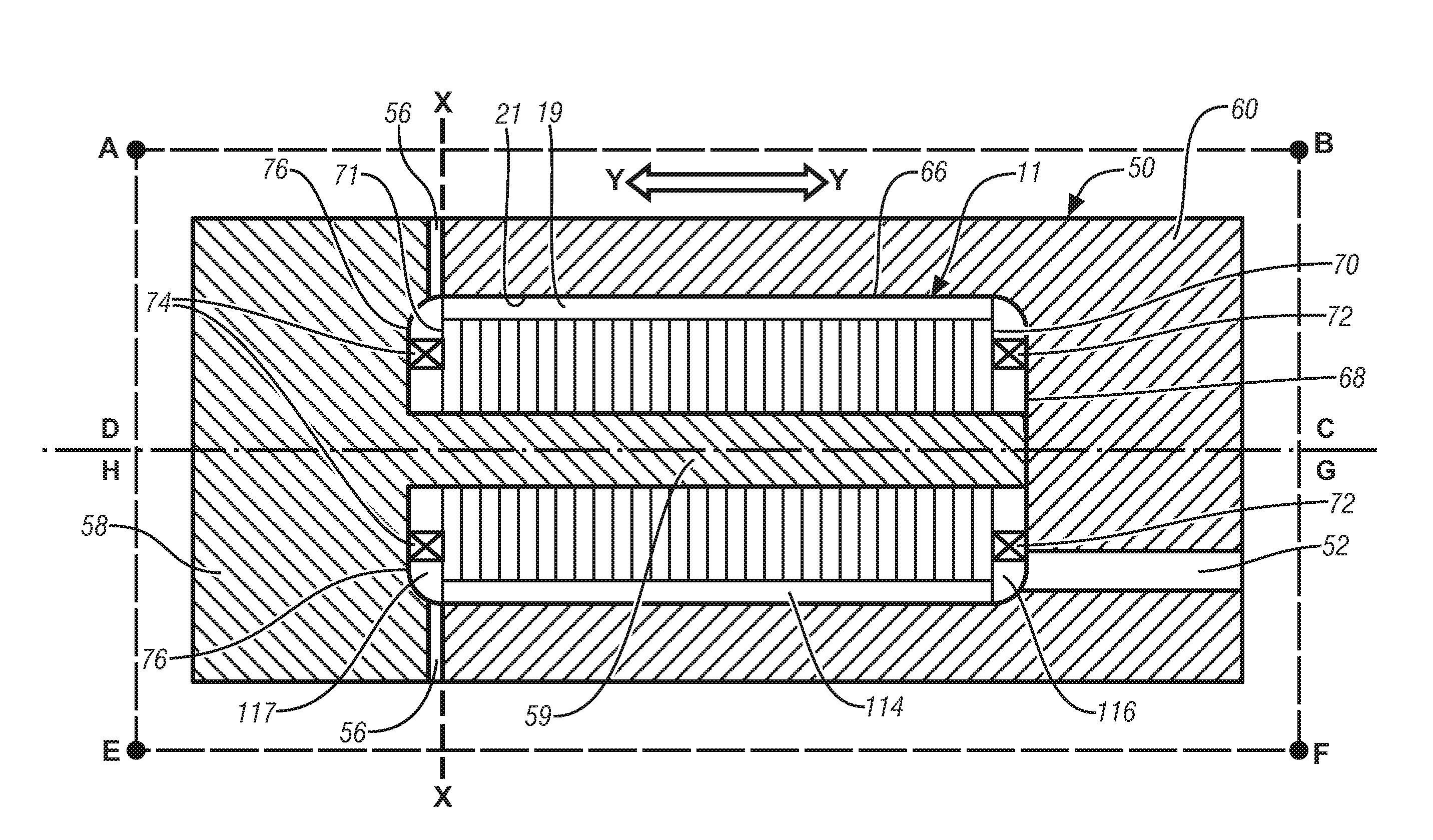
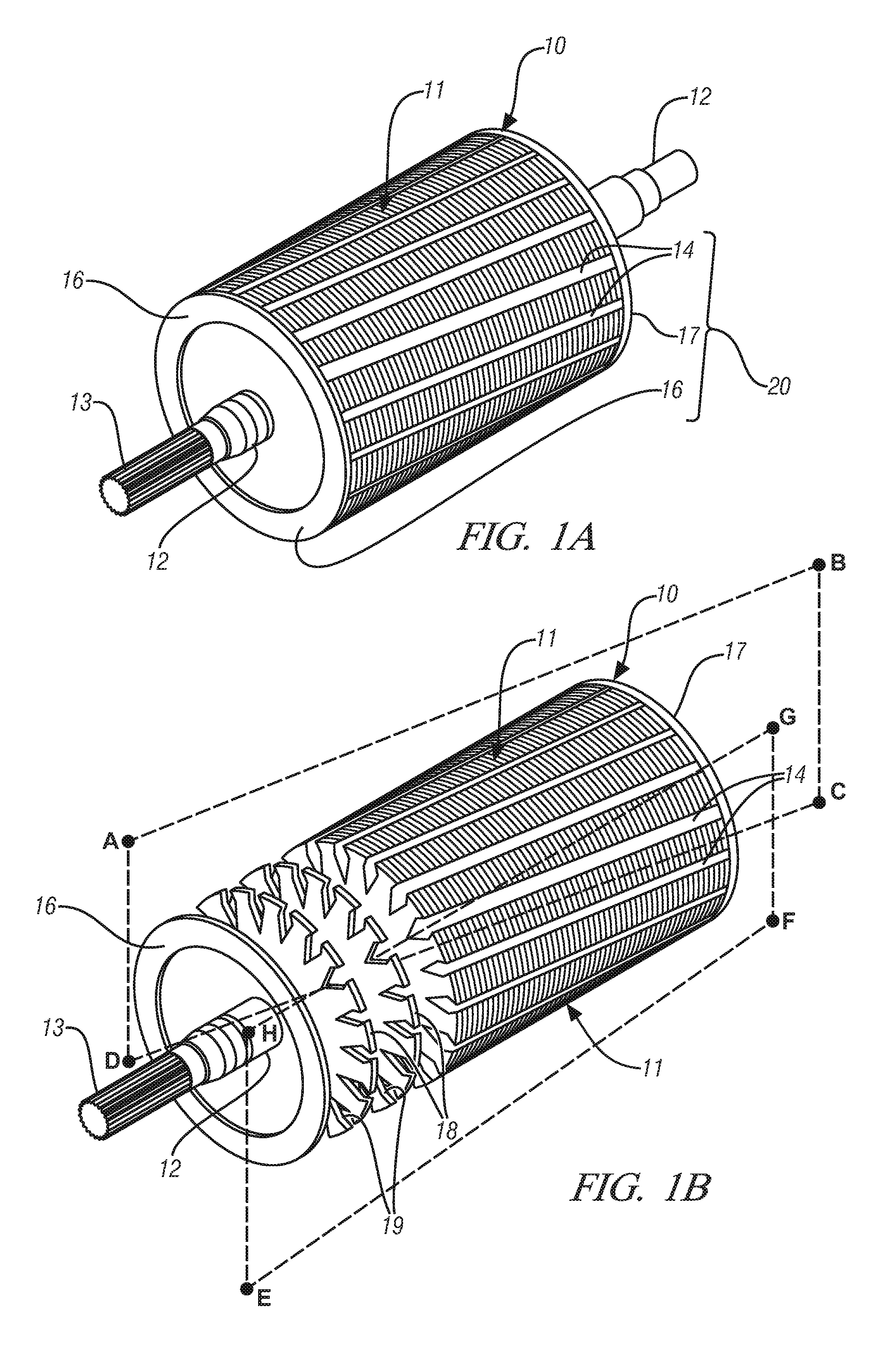
[0023]Induction motors operate through the repulsive interaction of a rotating electrically-generated magnetic field in a stator with an induced magnetic field arising from the induced current in an arrangement of conductors positioned on the rotor. Induction motors enjoy wide application and are available in a range of configurations depending primarily on their electrical rating but influenced also by packaging constraints. Thus many variants of the motor elements exist. In particular, the rotors may exhibit pronounced differences in length, diameter etc.

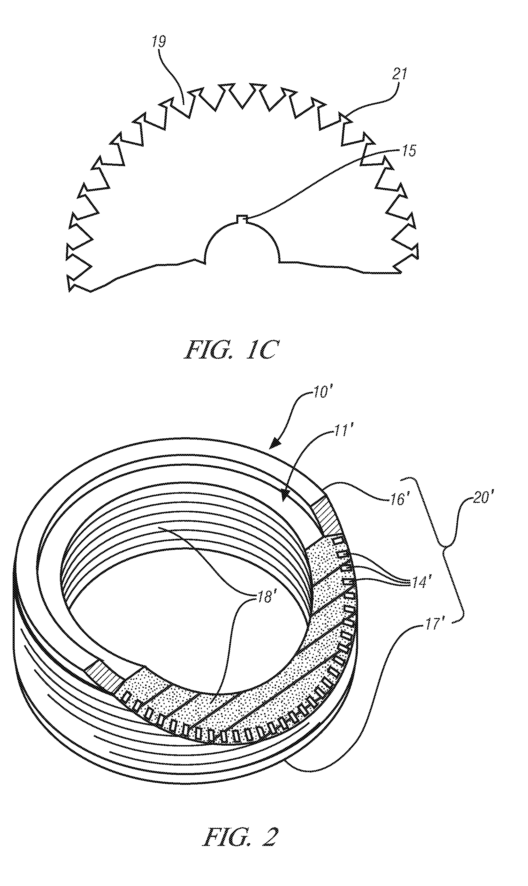
[0024]In common with other motors, particularly large motors suitable for automotive application, the magnetic forces are substantial and require that any conductors be restrained and securely anchored. Thus the rotor conductors are typically not positioned on the surface of the rotor but are instead embedded, partially or completely, within the rotor so that they may be well supported by the rotor structure.

[0025]A typical rotor ...


PUM

PropertyMeasurementUnit
weight percentaaaaaaaaaa
sizeaaaaaaaaaa
sizeaaaaaaaaaa

Abstract

A procedure for centrifugally casting a shorted structure around induction motor rotors is described. The method is commonly applied to a plurality of rotors disposed and arranged for rotational balance and supported on a suitable support, or optionally, on a plurality of supports arranged in layered fashion about a common rotational axis. The method comprises forming a wax representation of the shorted structure around a lamination stack; mounting a plurality of such lamination stacks in a mounting fixture and-attaching a suitable gating and runner system; forming an investment by coating the structure with refractory followed by melting out the wax; casting molten metal into the investment while it is rotating and aligning the mold to allow the centrifugal force generated to promote mold filling; and, continuing to rotate the investment until solidification is substantially complete.

Description

TECHNICAL FIELD[0001]This application relates to processes for forming shorted structures comprising conductor bars and end rings on laminated cores of rotors for induction motors. More specifically, this disclosure relates to investment casting of shorted structures on rotor cores using rotating mold assemblies by which pairs of rotors may be produced at the same time.BACKGROUND OF THE INVENTION[0002]One candidate electric motor type for driving wheels of electric and hybrid vehicles is the induction motor. Induction motors, of course, may be designed in many different sizes and shapes for delivering rotational power.[0003]A typical induction motor has a stationary annular wire-wound outer member of designed diameter and length called a stator. Often a three-phase alternating current is delivered to electrical leads of the stator so as to produce a magnetic field that rotates around the stator ring. A cylindrical rotor member carried on the rotating power shaft for the motor is pla...

Claims


Application Information

Patent Timeline
Patent Type & Authority Patents(United States)
IPC IPC(8): H02K15/02
CPCB22C9/04B22D13/06H02K15/0012Y10T29/49012Y10T29/49009
Inventor BIEDERMAN, SCOTT W.OSBORNE, MARK A.WALKER, MICHAEL J.PERRY, THOMAS A.
Owner GM GLOBAL TECH OPERATIONS LLC
Why Eureka
Try Eureka