High density front panel optical interconnect

a front panel and optical interconnect technology, applied in the field of electronic systems, can solve the problems of optical fiber alignment with much higher precision than electrical conductors, system is too big to fit in a single enclosure, and one unit containing all the necessary circuitry is too large to easily fit within a single enclosure, etc., and achieves the effect of small bend and high density

a front panel and optical interconnect technology, applied in the field of electronic systems, can solve the problems of optical fiber alignment with much higher precision than electrical conductors, system is too big to fit in a single enclosure, and one unit containing all the necessary circuitry is too large to easily fit within a single enclosure, etc., and achieves the effect of small bend and high density

US8348516B2Inactive Publication Date: 2013-01-08AMPHENOL CORP

Image

  • High density front panel optical interconnect
  • High density front panel optical interconnect
  • High density front panel optical interconnect

Examples


Embodiment Construction

[0048]In describing a preferred embodiment of the invention illustrated in the drawings, specific terminology will be resorted to for the sake of clarity. However, the invention is not intended to be limited to the specific terms so selected, and it is to be understood that each specific term includes all technical equivalents that operate in a similar manner to accomplish a similar purpose. In addition, it should be understood that the directions referred to here are with respect to the embodiments shown in the figures for ease of description. For instance, the terms “vertical,”“horizontal,”“x-direction,”“y-direction,”“z-axis,”“left,”“right,”“top,”“bottom,” and “side” are not intended to be limiting to the invention.

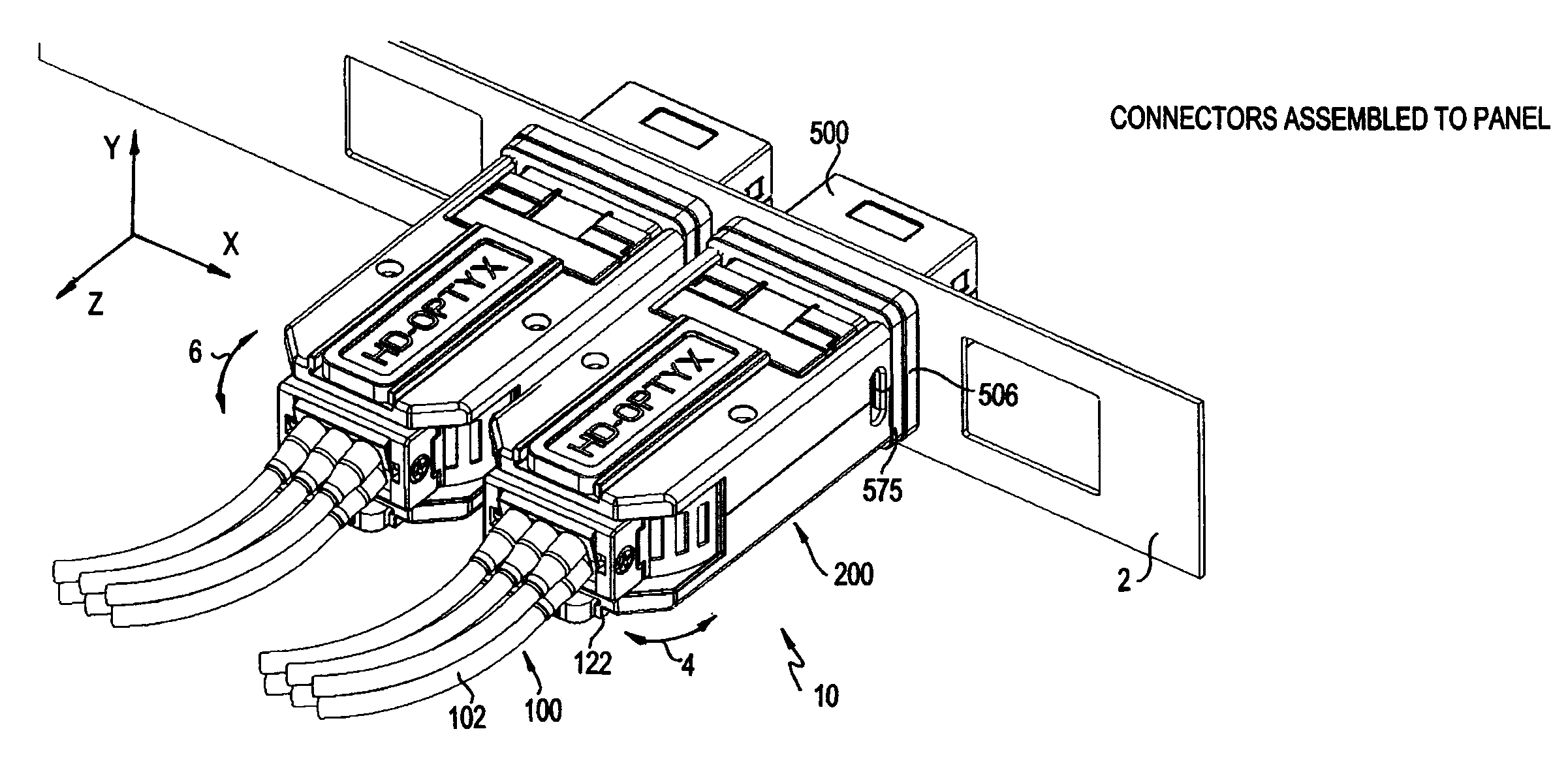
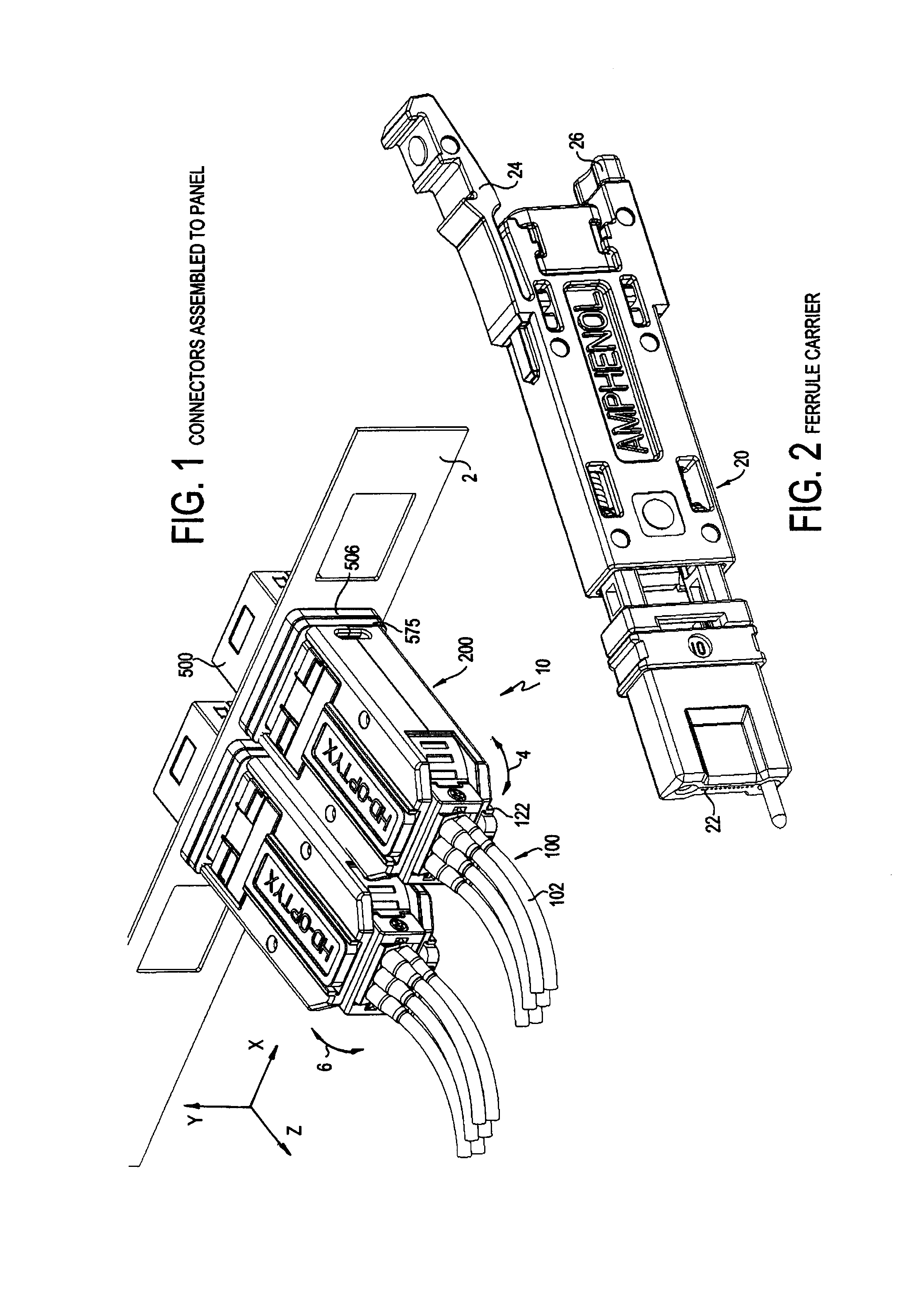
[0049]Turning to the drawings, FIG. 1 shows the connector assembly 10 in accordance with a preferred embodiment of the invention. As shown, the connector assembly 10 includes a cable assembly 100, plug assembly 200 and a socket assembly 500. The socket assembly 500 is a...


PUM


Abstract

A connector assembly has a cable assembly, plug assembly and a socket assembly. The socket assembly is a female member which is received within an opening at the front face of a panel. The plug assembly is a male member which then engages the socket at the front face of the panel. The cable assembly connects the cables carrying optical fibers to the plug assembly. As the socket assembly receives the plug assembly, doors on the respective housings open and ferrule carriers carried by the socket and plug assemblies mate. The plug assembly has a movable front end which permits the fibers to move in both horizontal and vertical directions.

Description

BACKGROUND OF THE INVENTION[0001]1. Field of the Invention[0002]The present invention relates generally to electronic systems and more particularly to electronic systems using optical fibers to carry data between components of the system.[0003]2. Background of the Related Art[0004]Common examples of electronic systems are computers, routers and telecommunications switches. Complex electronic systems have long been built as subassemblies that are then integrated into an overall system. Integration requires that data be passed between subassemblies. Traditionally, integration of subassemblies has included making connections for electrical signals to carry data between the subassemblies. In some systems, printed circuit boards, sometimes called backplanes, are used to carry electrical signals between subassemblies. Backplanes are usually built as printed circuit boards. Conductive traces within the board carry electrical signals and electrical connectors attached to the board allow sub...

Claims


Application Information

Patent Timeline
08 Jan 2013
Publication
US8348516B2
IPC
G02B6/36
CPC
G02B6/3823; G02B6/3827; G02B6/3849; G02B6/3897
Inventors
ROTH, RICHARD F.