
Double balun dipole

a dipole radiator and balun technology, applied in the direction of antennas, antenna details, antenna feed intermediates, etc., can solve the problems of reducing the axial ratio, and requiring conductive contact of radiators, so as to improve the bandwidth of dipole radiators, simplify and reduce the cost of construction, the effect of enhancing the bandwidth

Inactive Publication Date: 2013-01-08
THE UNITED STATES OF AMERICA AS REPRESENTED BY THE SECRETARY OF THE NAVY
View PDF9 Cites 17 Cited by
  • Summary
  • Abstract
  • Description
  • Claims
  • Application Information

AI Technical Summary

Benefits of technology

The double Marchand balun dipole antenna operates over a wider bandwidth, simplifies construction by eliminating the need for electrical continuity between elements, and maintains polarization purity, making it suitable for both coincident phase center and single-polarized applications.

Problems solved by technology

This interest has arisen from the difficulty of maintaining the axial ratio of circularly polarized beams when scanning off-axis.
With increasing bandwidth, compensating for this path difference becomes more difficult.
The difficulty with flared notches is that the individual radiators require conductive contact between adjacent elements to operate correctly at low frequencies within their design bandwidths
Employing elements which do not require conductive contract between adjacent elements may free the designer from the difficulties of maintaining electrical contact between adjacent elements, but may introduce problem of obtaining large bandwidths from elements not known for wide bandwidth.
The limits of the high frequency regime are encountered when interference between direct radiation from the dipoles, and reflected radiation from the ground plane behind the dipoles begins to form a null in the radiation pattern.
This antenna is difficult to build because it must be constructed to maintain electrical continuity in multiple places for two interleaved perpendicular polarizations simultaneously.
The difficulty with parallel wire transmission lines is that they must be protected from the rest of the world.
A conductor that is allowed too close can cause reflections or permit extra modes to propagate, and dielectrics can change the characteristic impedance or introduce losses.
Direct connections between balanced and unbalanced transmission lines generally result in undesirable large reflections.
However, as I pointed out above, balanced transmission lines are undesirable because they need to be shielded.
The self-shielding of unbalanced transmission lines reduces the coupling to nearby transmission lines.
The balanced transmission line mode of Munk et al. and Munk's dipole still needs to be converted to an unbalanced mode.
Practical circuit processing techniques limit how small features of a circuit can be made.

Method used


Image

  • Double balun dipole
  • Double balun dipole
  • Double balun dipole

Examples


Embodiment Construction

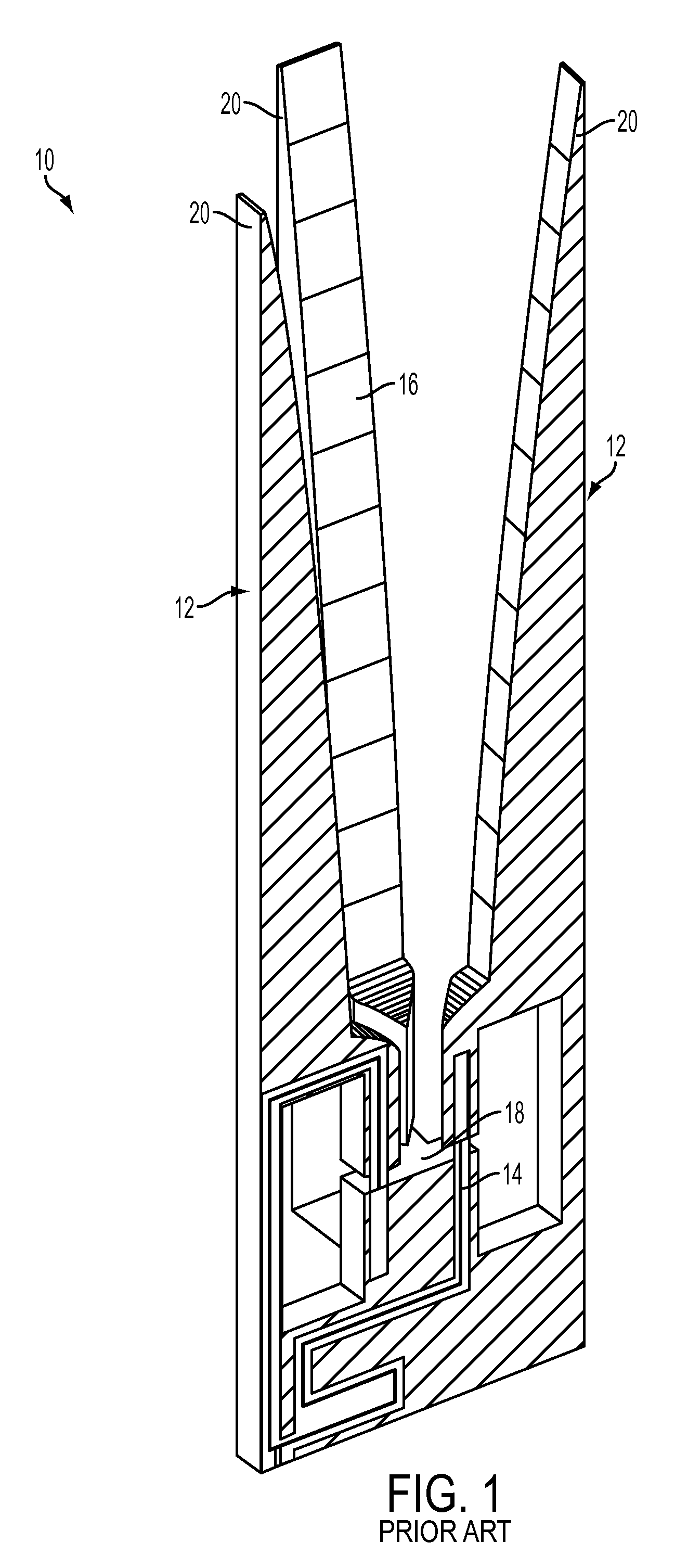
[0045]Before going into detail on operation and construction of the double Marchand balun dipole of the invention, it may be helpful to elaborate on the difference between a regular tee and E-plane tee. The term “E-plane tee” is borrowed from waveguide usage. Both type of transmission line tees are shown in FIGS. 7A-B. The tee in FIG. 7A is a regular tee. The electric field has the same polarity at both outputs. The tee in FIG. 7B is an E-plane tee. The electric field at the outputs has opposite polarity. Both tees can be implemented with balanced transmission line topology. The E-plane tee cannot be implemented with unbalanced transmission line topology. This is because the roles the two conductors play, as “shield” and “center conductor” would have to be reversed at the two output arms.

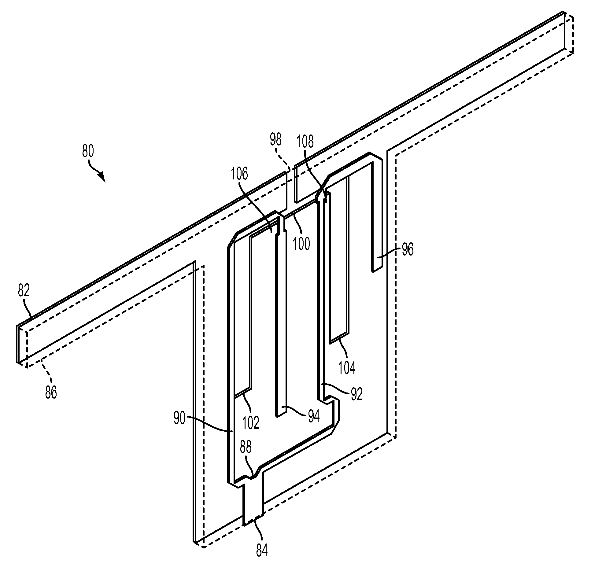
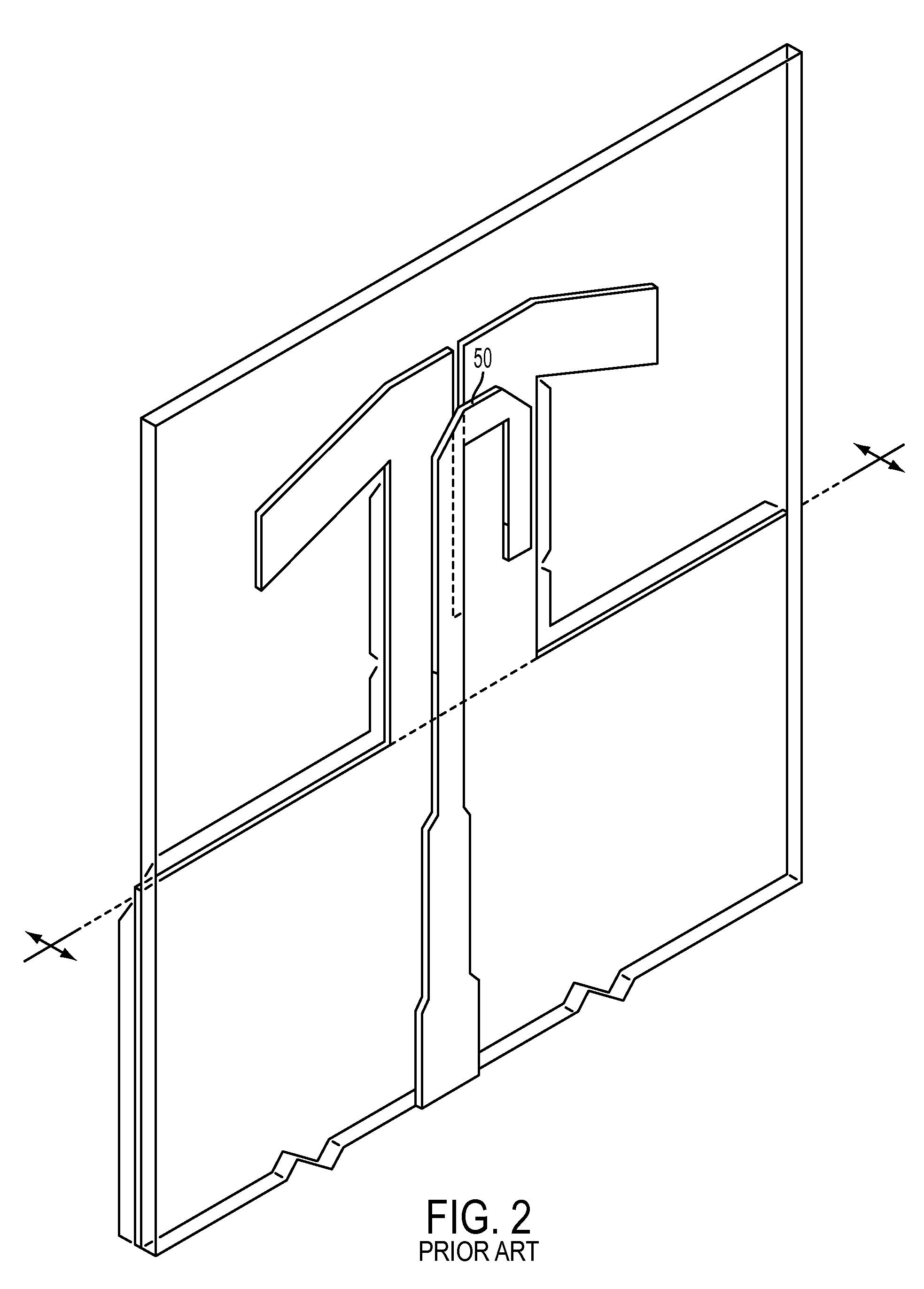
[0046]Referring back to FIG. 4, a double balun dipole can be implemented with either microstrip or stripline circuit methods. A double balun dipole 80 implemented with microstrip techniques is shown...


PUM


Abstract

A double balun dipole antenna element includes a dielectric substrate having a first surface and an opposing second surface, a pair of coplanar Marchand baluns positioned in a mutually antiphase configuration on the first and second surfaces, and at least one feed line connected to the pair of Marchand baluns. A doubly polarized antenna element includes a pair of orthogonally interleaved double balun dipole antenna elements, which can be further configured into an array of such antenna elements.

Description

CROSS-REFERENCE TO RELATED APPLICATIONS[0001]This Application is a Non-Prov of Prov (35 USC 119(e)) application 60 / 972,422 filed on Sep. 14, 2007.TECHNICAL FIELD[0002]The present invention is directed to an antenna element for an ultra wideband array antenna. More particularly, the invention is directed to a double Marchand balun dipole antenna element for an antenna array.BACKGROUND OF THE INVENTION[0003]There has been increasing interest in coincident phase center elements for electronically steered, polarization diverse, ultra wideband array antennas in recent years. This interest has arisen from the difficulty of maintaining the axial ratio of circularly polarized beams when scanning off-axis. When the constituent linear polarizations used to form circular polarization have adjacent phase centers, an angle dependant path length difference is introduced upon scanning. With increasing bandwidth, compensating for this path difference becomes more difficult. The motivation for devel...

Claims


Application Information

Patent Timeline
Patent Type & Authority Patents(United States)
IPC IPC(8): H01Q9/28
CPCH01Q9/16
Inventor PICKLES, WILLIAM R.
Owner THE UNITED STATES OF AMERICA AS REPRESENTED BY THE SECRETARY OF THE NAVY
Learn More