Method and system for controlling fuel usage

a fuel consumption and fuel technology, applied in the direction of electrical control, process and machine control, instruments, etc., can solve the problems of engine efficiency degrade, engine combustion stability and efficiency decline, and difficulty in transient control of egr, so as to reduce exhaust emissions and reduce the effect of rising prices of conventional fuels

Active Publication Date: 2013-01-08
FORD GLOBAL TECH LLC
View PDF47 Cites 29 Cited by
  • Summary
  • Abstract
  • Description
  • Claims
  • Application Information

AI Technical Summary

Benefits of technology

[0003]Engines may be configured with exhaust gas recirculation (EGR) systems to divert at least some exhaust gas from an engine exhaust to an engine intake. For example, an EGR valve may be actuated to adjust an amount of exhaust gas that is recirculated to the engine intake. While providing a desired engine dilution, such EGR systems may improve engine performance by reducing engine knock, throttling losses, heat transfer losses, as well as NOx emissions.
[0004]However, the inventors herein have recognized that EGR transients may be generated during engine operating conditions when a sudden increase or decrease in the amount of EGR desired occurs. Transient control of EGR is difficult, due to the delay between the time of actuation of an EGR valve and the corresponding change in dilution at the cylinder. For example, in response to a sudden tip-in from light load to medium load, an EGR valve may be adjusted to increase an amount of EGR provided. However, until the EGR gases mix with intake air throughout the intake manifold and the amount of EGR at the cylinders reaches the new desired amount, engine efficiency may be degraded. Similarly, in response to a sudden tip-out from medium load to light load, an EGR valve may be adjusted to decrease an amount of EGR provided. However, until the amount of EGR pre-mixed with air in the intake manifold is consumed by the cylinders, the actual EGR level in the cylinders will be higher than desired, and engine combustion stability and efficiency may be degraded.
[0006]In one example, an engine may be configured with a turbocharger for providing a boosted air charge, as well as an exhaust gas recirculation (EGR) passage for diverting at least some exhaust gas from the engine exhaust to the engine intake. In one example, the EGR passage may be configured to provide low pressure (LP) EGR wherein the exhaust gas is recirculated from the exhaust downstream of a turbocharger turbine to the intake upstream of a turbocharger compressor. In an alternate embodiment, the EGR passage may be configured to provide high pressure (HP) EGR wherein the exhaust gas is recirculated from the exhaust upstream of the turbocharger turbine to the intake downstream of the turbocharger compressor. The engine may also be configured with a direct injector for direct injecting a knock control fluid into an engine cylinder. In one example, the injected fluid may be water. In alternate examples, the injected fluid may be an alcohol-gasoline fuel blend or an alcohol fuel such as ethanol or methanol, or a mixture of one or more of these fuels with water. Herein, the inherent octane effects and / or the charge cooling effects and / or the dilution effects of the direct injected fluid may be used to address cylinder knock, reduce engine NOx emissions, and / or provide at least some engine dilution.
[0008]In response to a sudden increase or decrease in the desired amount of dilution, an EGR valve in the EGR passage may be actuated to increase or decrease the provided amount of EGR. Further, to compensate for EGR transients that may arise due to the delay between the actuation of the EGR valve and the change in engine dilution at the cylinder, an amount of knock control fluid, for example, water, direct injected into the cylinder may be increased (for example, from a first amount) to provide the required difference in engine dilution substantially immediately. As such, the amount of water direct injected may be adjusted to reflect an amount required to address engine knock at the prevalent engine operating conditions as well as to provide a dilution to reduce EGR transient control problems. Herein, by direct injecting water into the cylinder, a substantially immediate vaporization of the injected water into vapor may be achieved, thereby providing a faster change in engine dilution as compared to the actuation of the EGR valve.
[0014]In one example, the combination of effects may be inferred from the molar or volumetric composition of the injected fluid. For example, where the injected fluid is a blend including an alcohol fuel, the molar composition may be based on the volumetric fractions of the constituent fluids in the fuel blend, as well as their molecular weights and densities. Thus, as the alcohol content of the injected fluid increases, the inherent octane effect and charge cooling effects increase so direct injection amount for knock control may be decreased. Similarly, as the water content of the injected fluid increases, the dilution effect increases so the direct injection amount for dilution may be increased, and a smaller subsequent amount of VCT, and / or EGR dilution may be required.

Problems solved by technology

Transient control of EGR is difficult, due to the delay between the time of actuation of an EGR valve and the corresponding change in dilution at the cylinder.
However, until the EGR gases mix with intake air throughout the intake manifold and the amount of EGR at the cylinders reaches the new desired amount, engine efficiency may be degraded.
However, until the amount of EGR pre-mixed with air in the intake manifold is consumed by the cylinders, the actual EGR level in the cylinders will be higher than desired, and engine combustion stability and efficiency may be degraded.
To address sudden transients that may arise during the ramping out of EGR, for example, due to a sudden pedal tip-in or tip-out by the engine operator, the amount of dilution with EGR may be limited during steady state operation.
For example, at medium load the total desired dilution may be high, but achieving this dilution with EGR may not be feasible because it is impossible to quickly reduce the actual EGR at the cylinder in case of a subsequent tip-in or tip-out which may lead to a sudden decrease in desired dilution.

Method used


Image

  • Method and system for controlling fuel usage
  • Method and system for controlling fuel usage
  • Method and system for controlling fuel usage

Examples


Embodiment Construction

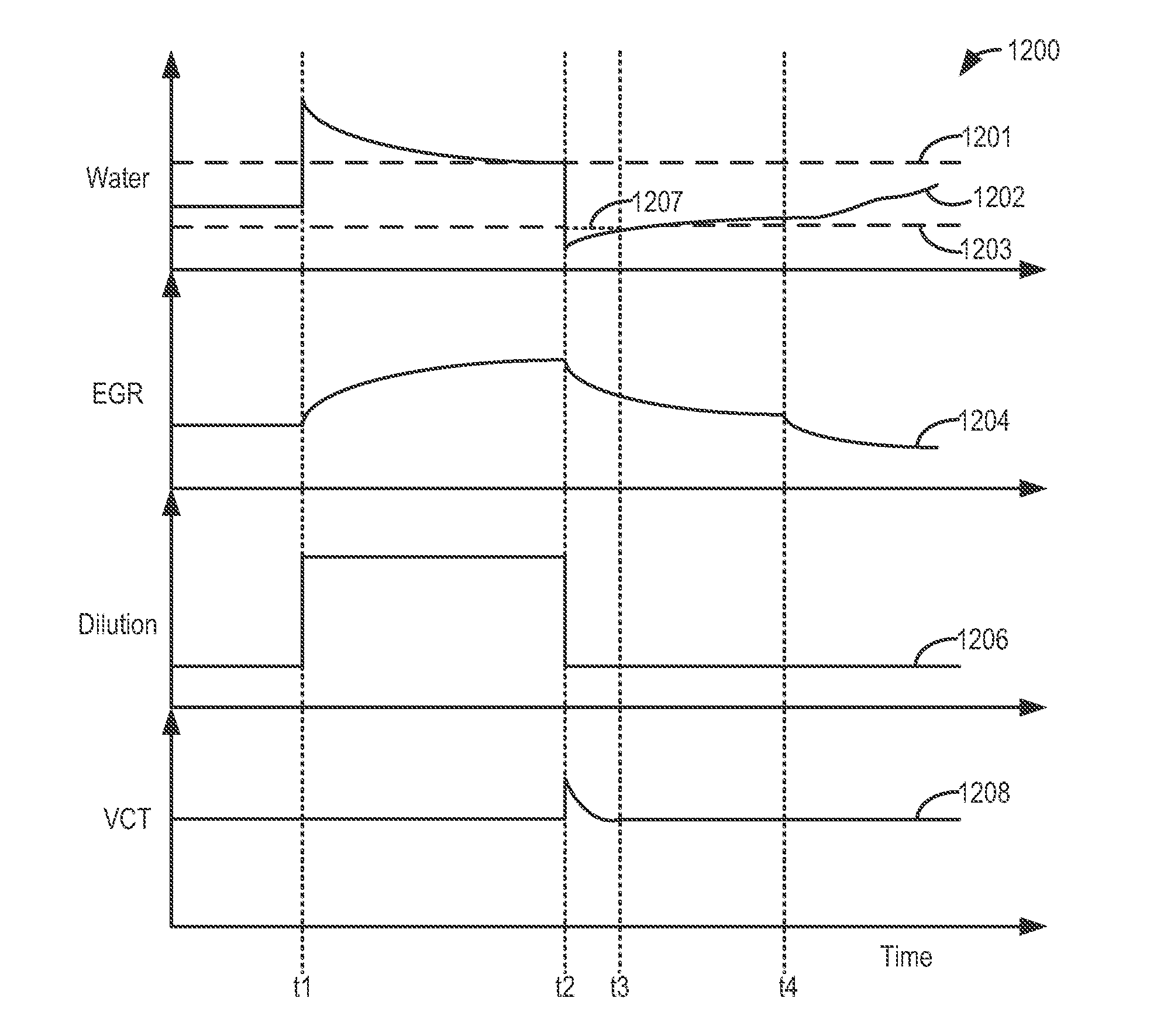
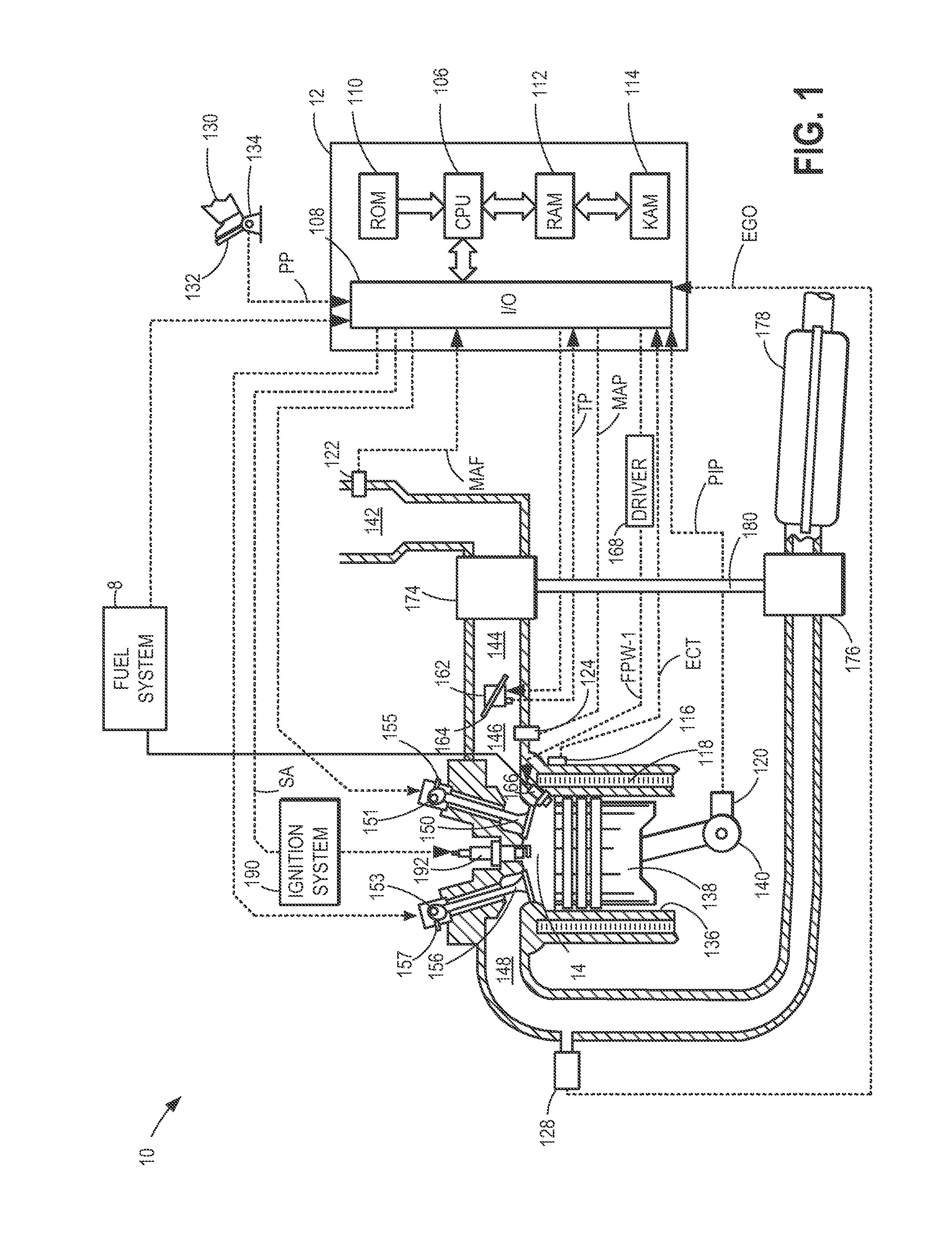
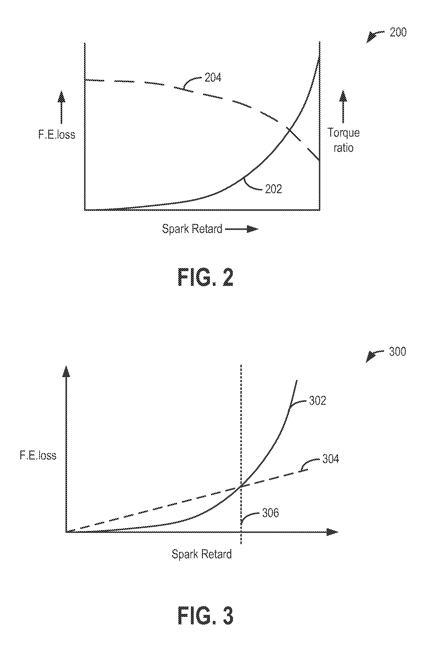
[0028]The following description relates to systems and methods for improving the efficiency of fuel usage in flex-fueled engines, such as the engine of FIG. 1. In response to engine knocking, an amount of spark retard and a knock control fluid injection may be used to address the knock. Specifically, spark may be retarded up to a predetermined amount of retard (such as a predetermined timing, or threshold point), up to which it may be more advantageous (e.g., more fuel economical) to use spark retard, and beyond which it may be more advantageous to inject a knock control fluid to address engine knock. As shown in FIGS. 2-5, based on a driver-selected cost function, a controller may adjust usage of spark retard and usage of direct injected and / or port injected fuels, or knock control fluids, to address knock. The usage may be further based on a combination of the inherent octane content, dilution effect, and charge cooling effect of the available knock control fluid(s), for example, ...


PUM


Abstract

Methods and systems are provided for improving fuel usage while addressing knock by adjusting the use of spark retard and direct injection of a fluid based on engine operating conditions and the composition of the injected fluid. One or more engine parameters, such as EGR, VCT, boost, throttle position, are coordinated with the direct injection to reduce torque and EGR transients.

Description

FIELD[0001]The present application relates to methods and systems for controlling use of various fuels in an internal combustion engine.BACKGROUND AND SUMMARY[0002]Alternate fuels have been developed to mitigate the rising prices of conventional fuels and for reducing exhaust emissions. For example, alcohol and alcohol-containing fuel blends have been recognized as attractive alternative fuels, in particular for automotive applications. Various engine systems may be used with alcohol fuels, utilizing various engine technologies and injection technologies. Further, various approaches may be used to control such alcohol-fuelled engines to take advantage of the charge-cooling effect of the high octane alcohol fuel, in particular to address engine knocking. For example, engine control methods may include adjustment of boost or spark timing in dependence upon the alcohol fuel, and various other engine operating conditions.[0003]Engines may be configured with exhaust gas recirculation (EG...

Claims


Application Information

Patent Timeline
Patent Type & Authority Patents(United States)
IPC IPC(8): G06F17/00F02B47/02F02B47/08
CPCF02B47/02F02D35/027F02D41/0025F02M25/03F02P5/152F02P5/1527F02M25/0227F02B47/08F02D41/1498F02D2200/0612Y02T10/46F02D2041/0075Y02T10/40
Inventor LEONE, THOMAS G.SURNILLA, GOPICHANDRA
Owner FORD GLOBAL TECH LLC
Why Eureka
Try Eureka