
Mass spectrometer

a mass spectrometer and mass spectrometer technology, applied in mass spectrometers, calibration apparatus, particle separator tubes, etc., can solve the problems of significant number of ion arrival events not being recorded, significant time interval or dead-time, and inability to distinguish between signals, etc., to achieve increased dynamic range, increased dynamic range, and increased dynamic range

Active Publication Date: 2013-01-15
MICROMASS UK LTD
View PDF16 Cites 26 Cited by
  • Summary
  • Abstract
  • Description
  • Claims
  • Application Information

AI Technical Summary

Benefits of technology

The present invention provides a method for detecting ions using a combination of two signals, where each signal is multiplied or amplified by a different gain. The two signals are then digitised and combined to form a final spectrum. The method can detect peaks or ion arrival events in the signals and determine their mass or mass to charge ratio data. The method can also process the signals to detect specific peaks or ion arrival events. The technical effect of this invention is to provide a more accurate and reliable method for detecting ions.

Problems solved by technology

One disadvantage of Time to Digital Converters is that once an ion event has been recorded then there is a significant time interval or dead-time following the ion arrival event during which time no further ion arrival events can be recorded.
Another important disadvantage of Time to Digital Converters is that they are unable to distinguish between a signal resulting from the arrival of a single ion at the ion detector and a signal resulting from the simultaneous arrival of multiple ions at the ion detector.
At relatively high signal intensities the above mentioned disadvantages coupled with the problem of dead-time effects will result in a significant number of ion arrival events failing to be recorded and / or an incorrect number of ions being recorded.
This will result in an inaccurate representation of the signal intensity and an inaccurate measurement of the ion arrival time.
These effects have the result of limiting the dynamic range of the ion detector system.
However, the detection of low intensity signals is generally limited by electronic noise from the digitiser electronics, the ion detector and the amplifier system.
The problem of electronic noise also effectively limits the dynamic range of the ion detector system.
Another disadvantage of using an Analogue to Digital Converter as part of an ion detector system (as opposed to using a Time to Digital Converter as part of the ion detector system) is that the analogue width of the signal generated by a single ion adds to the width of the ion arrival envelope for a particular mass to charge value in the final spectrum.
However, these methods have the disadvantage of having a reduced duty cycle.
However, such an approach is difficult to implement and the ion detector system can suffer from cross-talk between the anodes.
There are, however, certain disadvantages inherent with the known technique.
Any errors in the gain of the amplifiers of the Analogue to Digital Converter input stages or DC offsets (amplifier or Analogue to Digital Converter) or signal synchronisation of the Analogue to Digital Converters relative to the trigger event can result in significant shifts in arrival time when the data from both Analogue to Digital Converters is combined.
Synchronisation between the two signals presented to the Analogue to Digital Converters is difficult to achieve at high frequencies of digitisation and attempts at correcting any time differences in the signal being digitised is, in effect, limited to one digitisation time interval which may be too coarse to be of any particular use.
The known method also suffers from the same problems as a standard averaging Analogue to Digital Converter system in terms of reduced dynamic range due to the averaging of noise at low signal intensities and degraded resolution due to the digitization of the analogue ion peak width.
However, such systems are relatively complex to calibrate and operate.
Such systems are also comparatively expensive.
However, although this technique does represent an improvement over previous known methods, it still suffers from a relatively limited dynamic range and at higher signal intensities it continues to suffer from saturation effects.
In addition, it is difficult using the known method to know with any certainty whether the signal has at any time during the acquisition saturated the Analogue to Digital Converter especially if the input signal changes significantly, in intensity during the time during which individual transients are being combined or integrated into a final spectrum (sometimes referred to as the scan time).
This can lead to mass accuracy and quantitation errors which are difficult to detect and correct.

Method used


Image

  • Mass spectrometer
  • Mass spectrometer
  • Mass spectrometer

Examples


Embodiment Construction

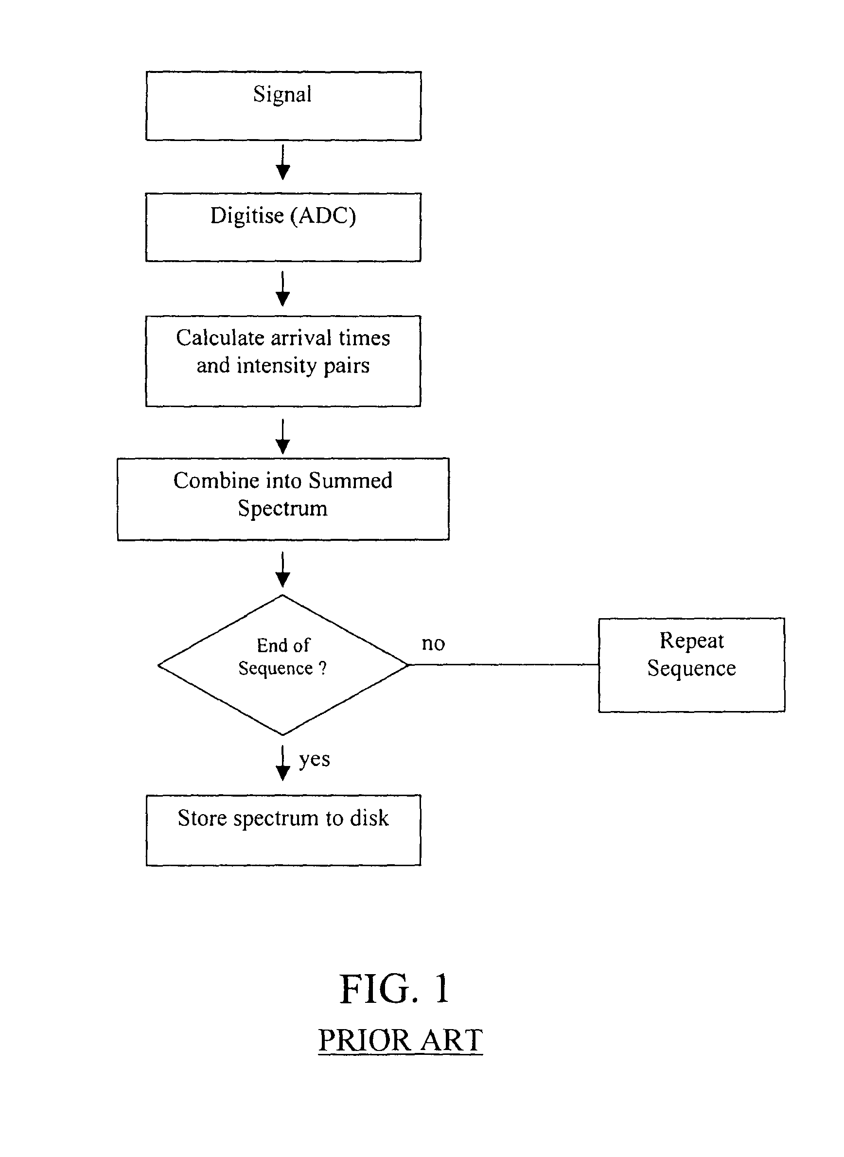
[0181]A flow diagram illustrating a known Analogue to Digital Converter ion detector system is shown in FIG. 1. An input transient signal resulting from a trigger event is digitised and converted into arrival time and intensity pairs at the end of each transients predefined record length. A series of arrival time and intensity pairs are combined with those of other mass spectra within a predefined integration period or scan time to form a single mass spectrum. Each mass spectrum may comprise many tens of thousands of transients.

[0182]A significant disadvantage of the known method is that it has a limited dynamic range and at relatively high signal intensities the Analogue to Digital Converter will suffer from saturation effects. It is also difficult to determine with any certainty whether or not the signal within an individual transient has saturated the Analogue to Digital Converter especially if the input signal changes significantly in intensity during the scan time. This frequen...


PUM


Abstract

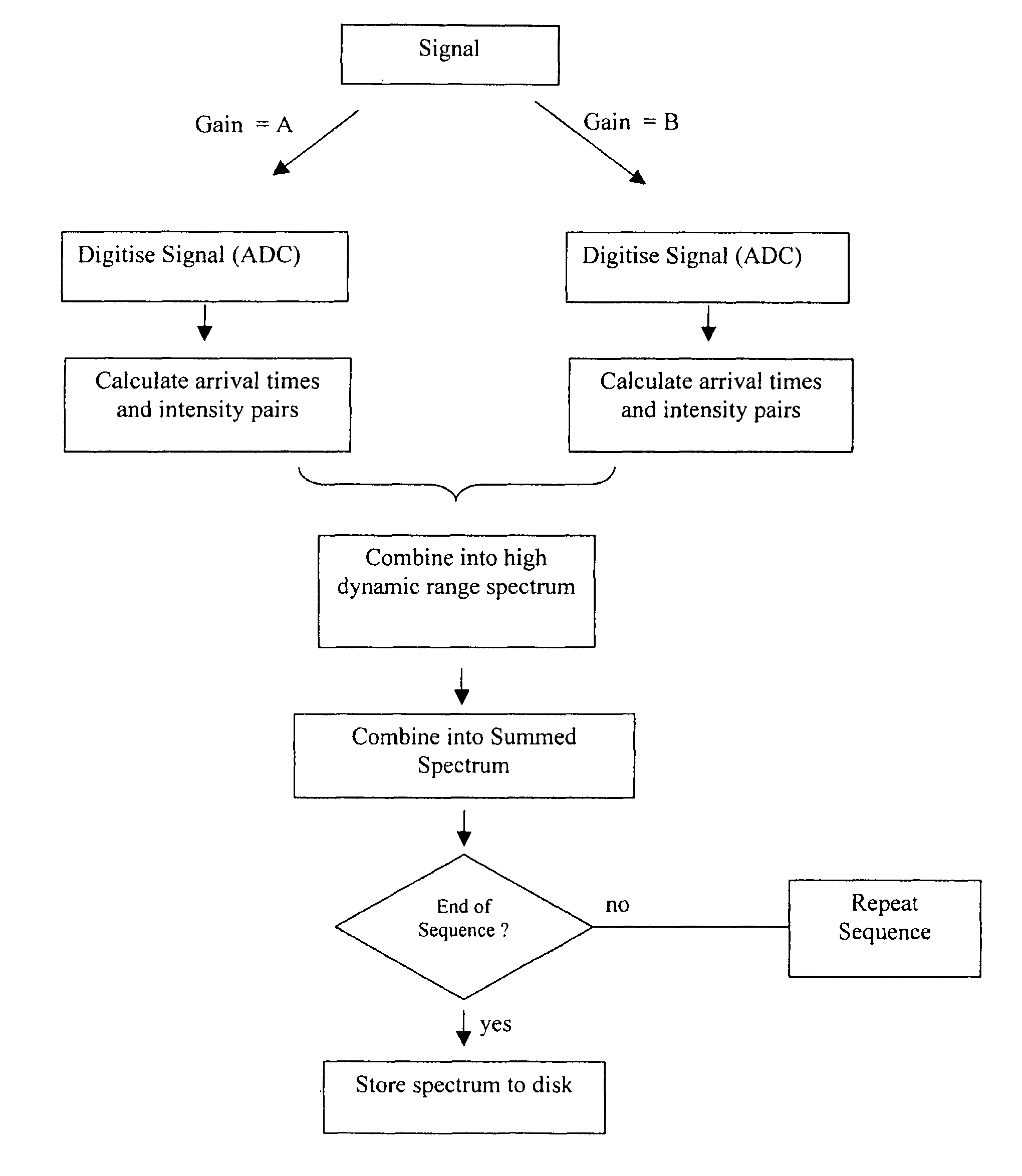
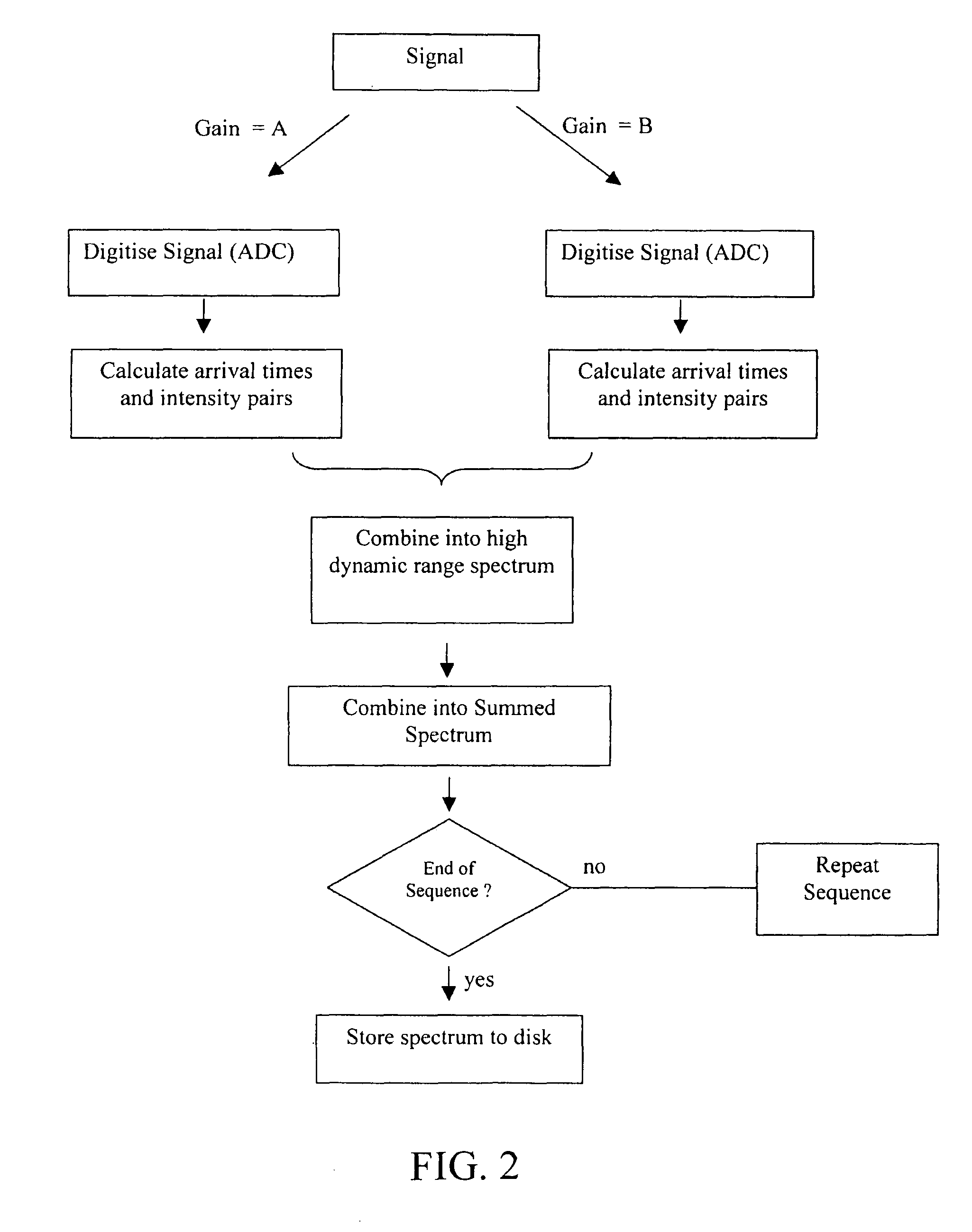
A mass spectrometer is disclosed wherein an ion signal is split into a first and second signal. The first and second signals are multiplied by different gains and are digitised. Arrival time and intensity pairs are calculated for both digitised signals and the resulting time and intensity pairs are combined to form a high dynamic range spectrum. The spectrum is then combined with other corresponding spectra to form a summed spectrum.

Description

CROSS REFERENCE TO RELATED APPLICATIONS[0001]This application is the National Stage of International Application No. PCT / GB2008 / 001756, filed May 22, 2008, which claims priority to and benefit of United Kingdom Patent Application No. 0709799.1, filed May 22, 2007, and U.S. Provisional Patent Application Ser. No. 601946,211, filed Jun. 26, 2007. The entire contents of these applications are incorporated herein by reference.BACKGROUND OF THE INVENTION[0002]The present invention relates to a mass spectrometer and a method of mass spectrometry. The preferred embodiment relates to an ion detector system and method of detecting ions.[0003]It is known to use Time to Digital Converters (“TDC”) and Analogue to Digital Converters (“ADC”) as part of data recording electronics for many analytical instruments including Time of Flight mass spectrometers.[0004]Time of Flight instruments incorporating Time to Digital Converters are known wherein signals resulting from ions arriving at an ion detect...

Claims


Application Information

Patent Timeline
Patent Type & Authority Patents(United States)
IPC IPC(8): B01D59/44H01J49/00
CPCH01J49/40H01J49/0036H01J49/022
Inventor GREEN, MARTINPRINGLE, STEVEN DEREKWILDGOOSE, JASON LEE
Owner MICROMASS UK LTD
Learn More