Centrifugal filter

a centrifugal filter and filter body technology, applied in the field of centrifugal filters, can solve the problems of conventional devices, and leakage of sleeves, and achieve the effects of reducing fluid height, low specific protein binding quality, and increasing membrane area

Active Publication Date: 2013-01-22
MILLIPORE CORP
View PDF46 Cites 20 Cited by
  • Summary
  • Abstract
  • Description
  • Claims
  • Application Information

AI Technical Summary

Benefits of technology

[0007]The problems of the prior art have been overcome by the present invention, which provides a filtration device particularly suited for concentration of liquid samples, particularly biomolecules, and a method of concentrating, desalting, purifying and / or fractionating liquid samples. More specifically, in certain embodiments the device includes a housing having a sample reservoir, and two substantially vertically oriented and spaced apart membranes disposed in the housing. An underdrain is associated with each membrane such that fluid passing through each membrane flows through a respective underdrain into a filtrate collection chamber. The fluid that does not pass through the membrane is collected in the retentate collection chamber, and can be recovered such as by a reverse spinning step, achieving recoveries greater than about 90%. The substantially vertical orientation of the membranes increases the available membrane area by at least 2.7 times the area available in a conventional MICROCON™ filter device. The two-panel configuration also maintains more available membrane area in use during the last stages of filtration than a one-panel configuration. Active membrane area is needed the most during the last stages of filtration, when the retentate sample becomes more concentrated and membrane surface fouling increases, membrane interior fouling increases, and the fluid height decreases. The device housing is preferably made of a low-cost material, has low specific protein binding qualities, and is disposable.

Problems solved by technology

However, the sleeves may crack and leak, which may be caused by stresses that occur at the knit line.
However, conventional devices suffer from various drawbacks, including lower than desired recovery, filtration speed, and / or high price.

Method used


Image

  • Centrifugal filter
  • Centrifugal filter
  • Centrifugal filter

Examples


Embodiment Construction

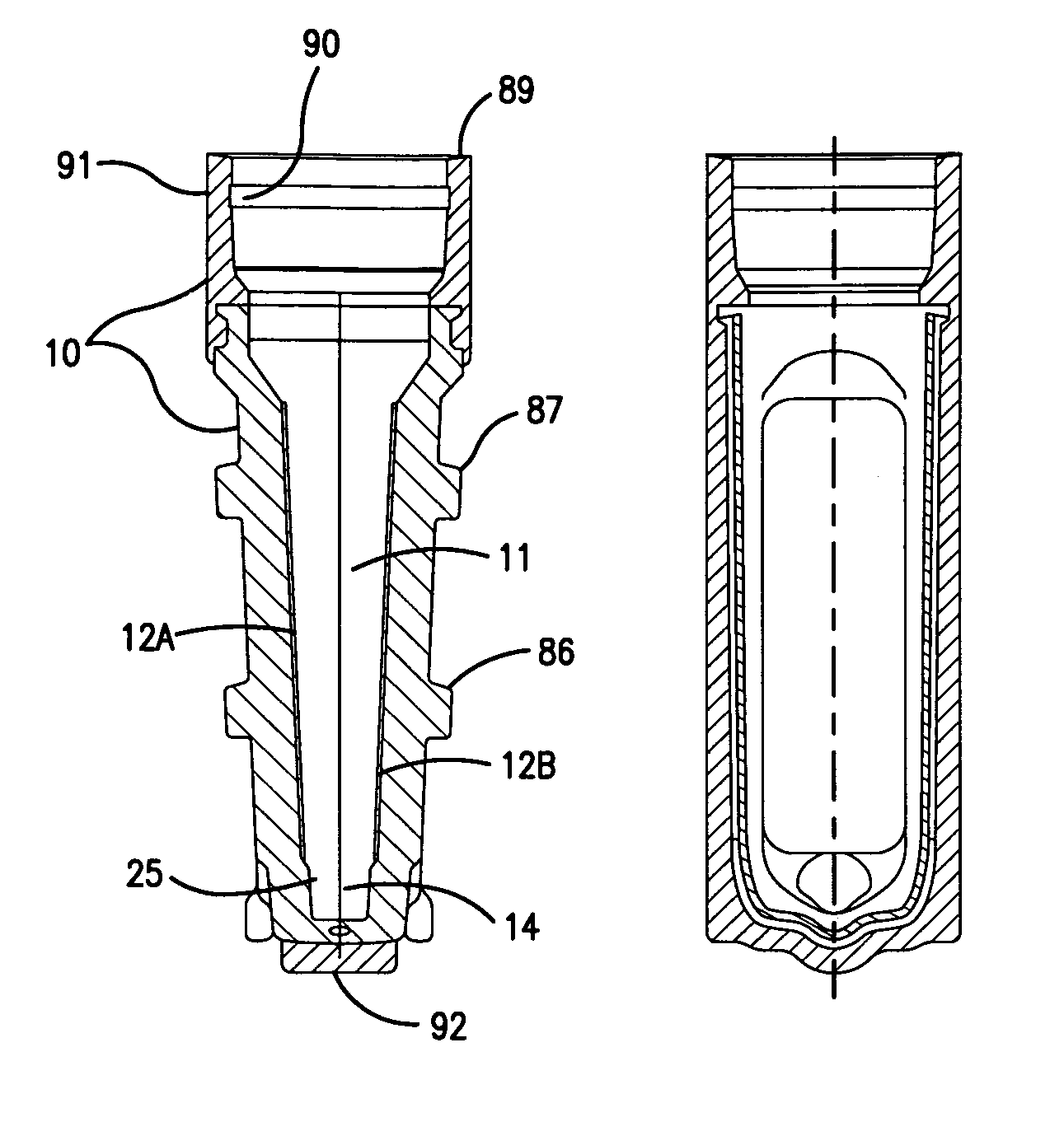
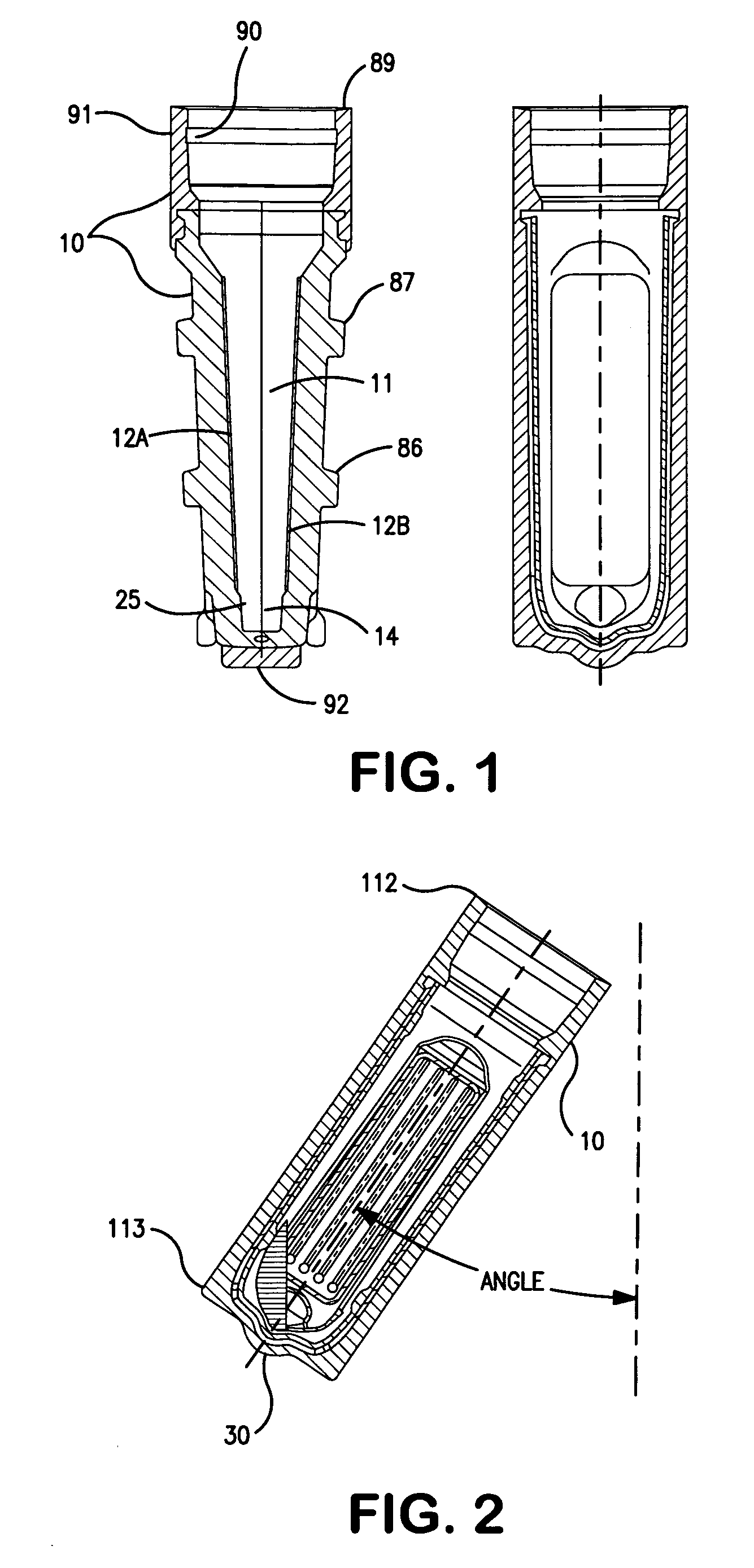
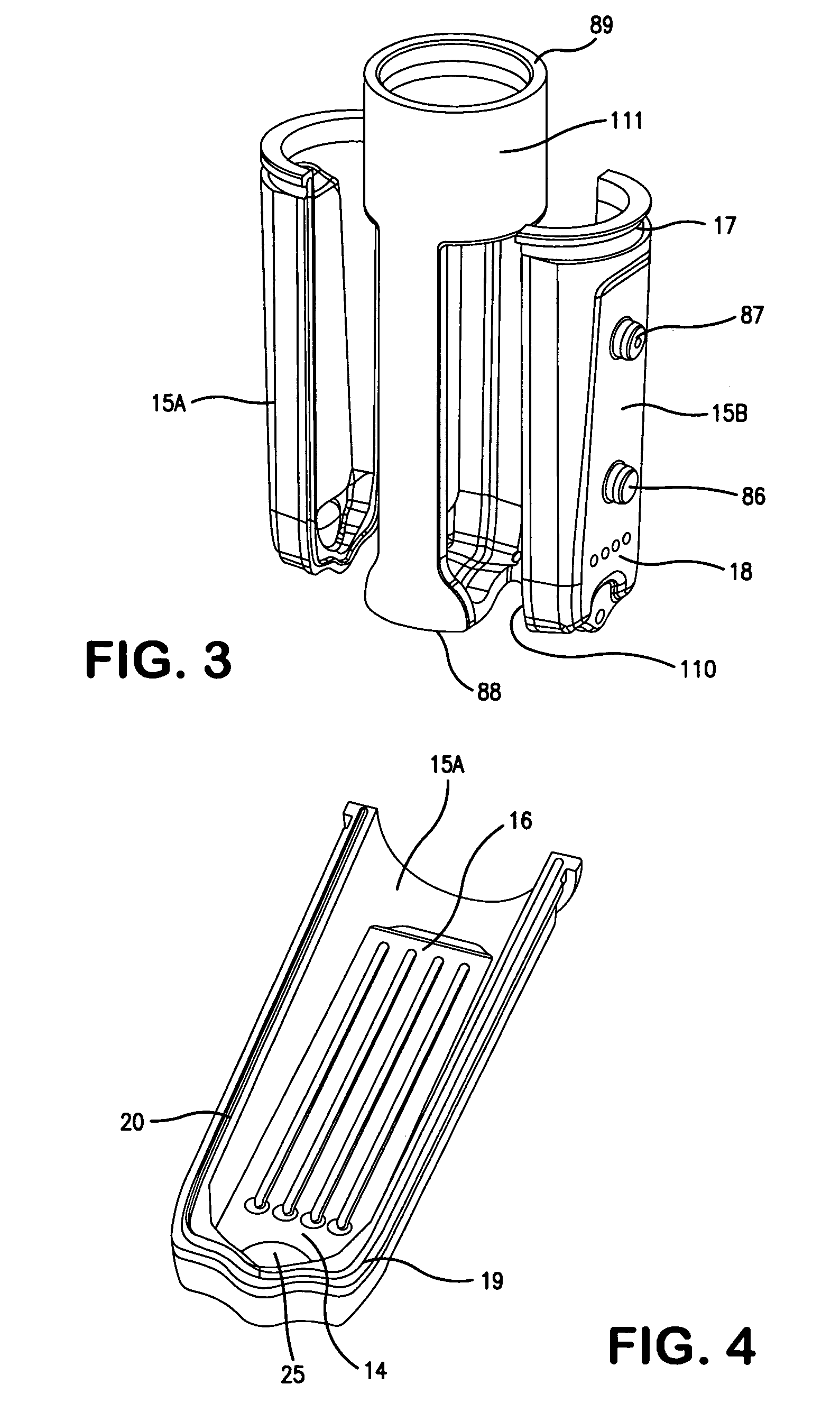
[0045]Turning first to FIG. 1, there is shown filter device 10. The device 10 includes a sample reservoir 11 to receive an unfiltered sample, and first and second membranes 12A and 12B each arranged on a side wall of the device 10 as shown. A retentate chamber 14 defining a dead-stop volume is provided below the membranes 12A and 12B. A collection tip 30 (FIG. 2) that is generally arc-shaped and protrudes outwardly from the bottom perimeter of the device may be provided to localize the dead-stop volume at the centerline of the device, and subsequently reduce variability of the dead-stop volume as the angle of orientation in a centrifuge changes. Preferably the device 10 is made of a solid material that is liquid impermeable, has low protein binding characteristics, and is sufficiently strong to withstand the gravitational forces (Gs) applied during centrifugation. Suitable materials include acrylic, CYROLITE G20 HiFlo resin, ESTAR HN631 resin and KRATON polymers. The side panels 15A...


PUM

PropertyMeasurementUnit
angleaaaaaaaaaa
angleaaaaaaaaaa
angleaaaaaaaaaa

Abstract

Filtration device suited for concentration of liquid samples, particularly biomolecules, and a method of concentrating, desalting, purifying and / or fractionating liquid samples. In certain embodiments the device includes a housing having a sample reservoir, and two substantially vertically oriented and spaced apart membranes disposed in the housing. An underdrain is associated with each membrane such that fluid passing through each membrane flows through a respective underdrain into a filtrate collection chamber. The fluid that does not pass through the membrane is collected in the retentate collection chamber, and can be recovered such as by a reverse spinning step, achieving recoveries greater than about 90%. The substantially vertical orientation of the membranes increases the available membrane area by at least 2.7 times the area available in a conventional filter device. The two-panel configuration also maintains more available membrane area in use during the last stages of filtration than a one-panel configuration.

Description

BACKGROUND OF THE INVENTION[0001]Centrifugal filters may be used to separate biological substances such as an antibody enzyme, nucleic acid and protein for the purpose of concentration, desalting, purification, and fractionation. These devices are most commonly used in centrifugal-separator instruments, which may consist of a fixed-angle-rotor configuration or a swing- or variable-angle-rotor configuration. The speed of the filtering process and the recovery of retentate sample are highly valued by customers. Sample recovery values higher than 85% are usually obtained by removing the membrane capsule (sample holder) and reverse spinning it in a receiver tube.[0002]Such devices are typically used to concentrate urine, serum, plasma and cerebrospinal fluid. For example, the measurement of specific proteins in urine can be important for the diagnosis and management of various disease states, yet the content of these proteins in urine is often too small to be detected without first conc...

Claims


Application Information

Patent Timeline
Patent Type & Authority Patents(United States)
IPC IPC(8): B01D63/08B01D25/22B01D21/26
CPCB01D61/18B01D63/16B01L3/5021B01L3/502B01L3/5635B01D61/145B01D63/08B01L2300/0681B01D2313/08
Inventor BONHOMME, LOUISDOYLE, JOHNGREENIZEN, KURTGAGNE, GEORGEDEVIN, SEANLOMBARD, GERARDSMITH, VINCENTKAVONIAN, MARK
Owner MILLIPORE CORP
Why Eureka
Try Eureka