
Systems and methods for distortion measurement using distortion-to-amplitude transformations

a technology of distortion and transformation, applied in the field of amplifier distortion measurement, can solve the problems of amplitude and phase distortion, higher bit error rate, crucial distortion effects of power amplifiers, etc., and achieve the effect of accurate measurement of distortion effects and reduction of test costs

Inactive Publication Date: 2013-01-22
GEORGIA TECH RES CORP
View PDF7 Cites 7 Cited by
  • Summary
  • Abstract
  • Description
  • Claims
  • Application Information

AI Technical Summary

Benefits of technology

This approach reduces testing costs while maintaining or improving accuracy, enabling real-time measurement of amplifier distortions without the need for complex instruments, and is applicable to various amplifier types in wireless and wireline systems.

Problems solved by technology

Power Amplifiers exhibit crucial distortion effects at high power, namely amplitude and phase distortions.
AM-AM distortion or gain compression causes intermodulation distortion (IMD) resulting in the folding of the out of band signal onto the desired signal spectrum, thereby resulting in higher bit error rate.
AM-PM distortion or phase distortion causes unequal rotation in the received constellation causing difficulties in signal detection.
The sum effect of AM-AM and AM-PM causes bit errors at the received signal as well as out of hand interference in the transmitted signal leading to violation of the defined FCC transmit spectral mask.
However accurate measurements of AM-PM effects require high precision instrumentation, and hence, are expensive and time consuming.
Besides cost and time (setup time and calibration time) considerations in this particular setup, the measurement is highly sensitive to calibration.

Method used


Image

  • Systems and methods for distortion measurement using distortion-to-amplitude transformations
  • Systems and methods for distortion measurement using distortion-to-amplitude transformations
  • Systems and methods for distortion measurement using distortion-to-amplitude transformations

Examples


Embodiment Construction

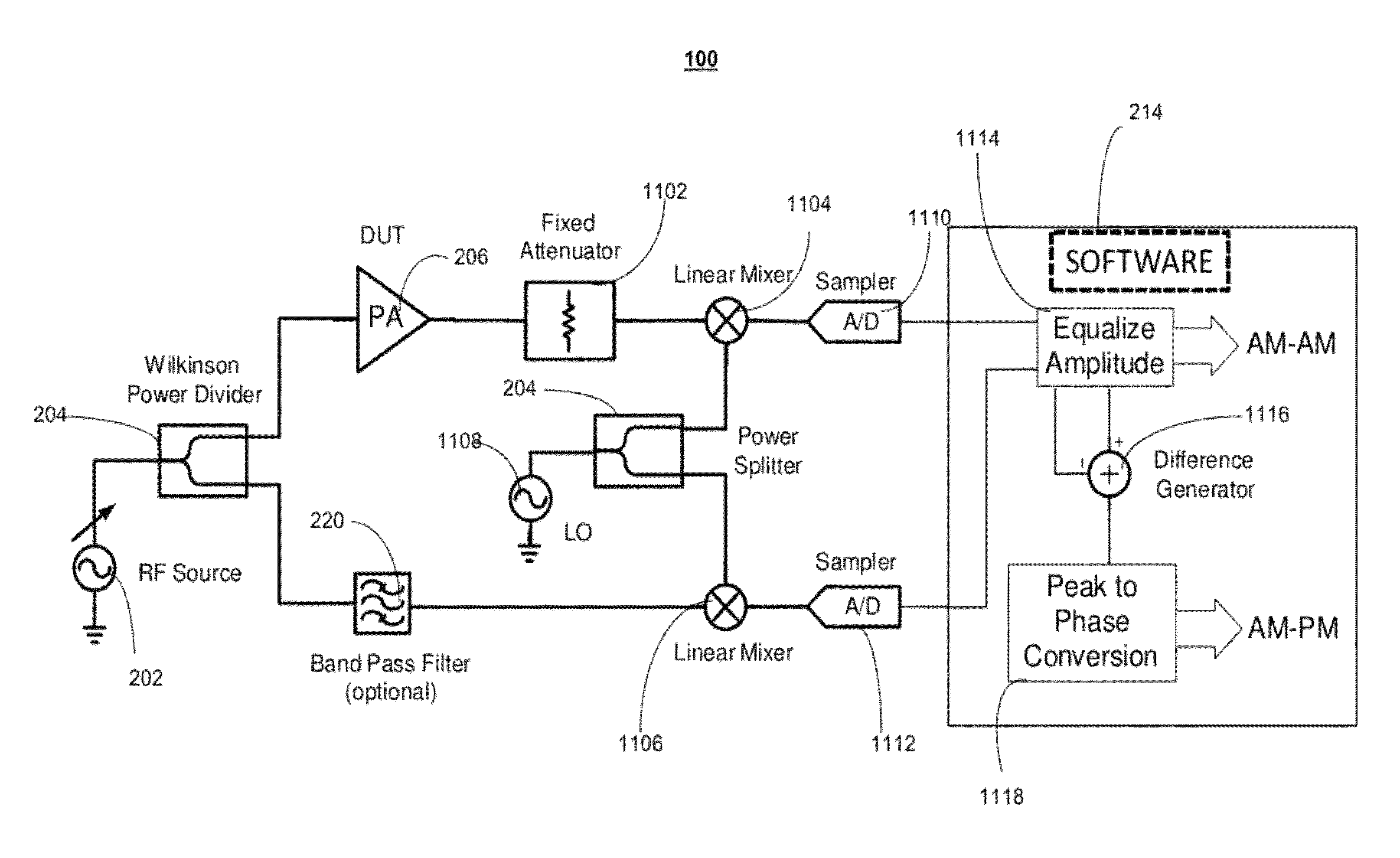
[0032]The present invention addresses the deficiencies in the prior art concerning the lack of a relatively low cost device or system to accurately measure amplitude and phase distortion in an amplifier. Significantly, the present invention provides methods and apparatus for providing cost efficient and effective amplifier distortion measurement systems using phase-to-amplitude conversion techniques. An amplifier distortion measurement system provided in accordance with the present invention is enabled to provide accurate measure of amplitude distortion and phase distortion with relatively simple hardware and / or software components compared to traditional network analyzers. Additionally, the present invention overcomes the drawbacks of the conventional methods and systems in the prior art and provides some embodiments of the systems and methods, which are enabled to utilize software and minimal hardware to calculate amplitude distortion and phase distortion in real-time.

[0033]An exe...


PUM


Abstract

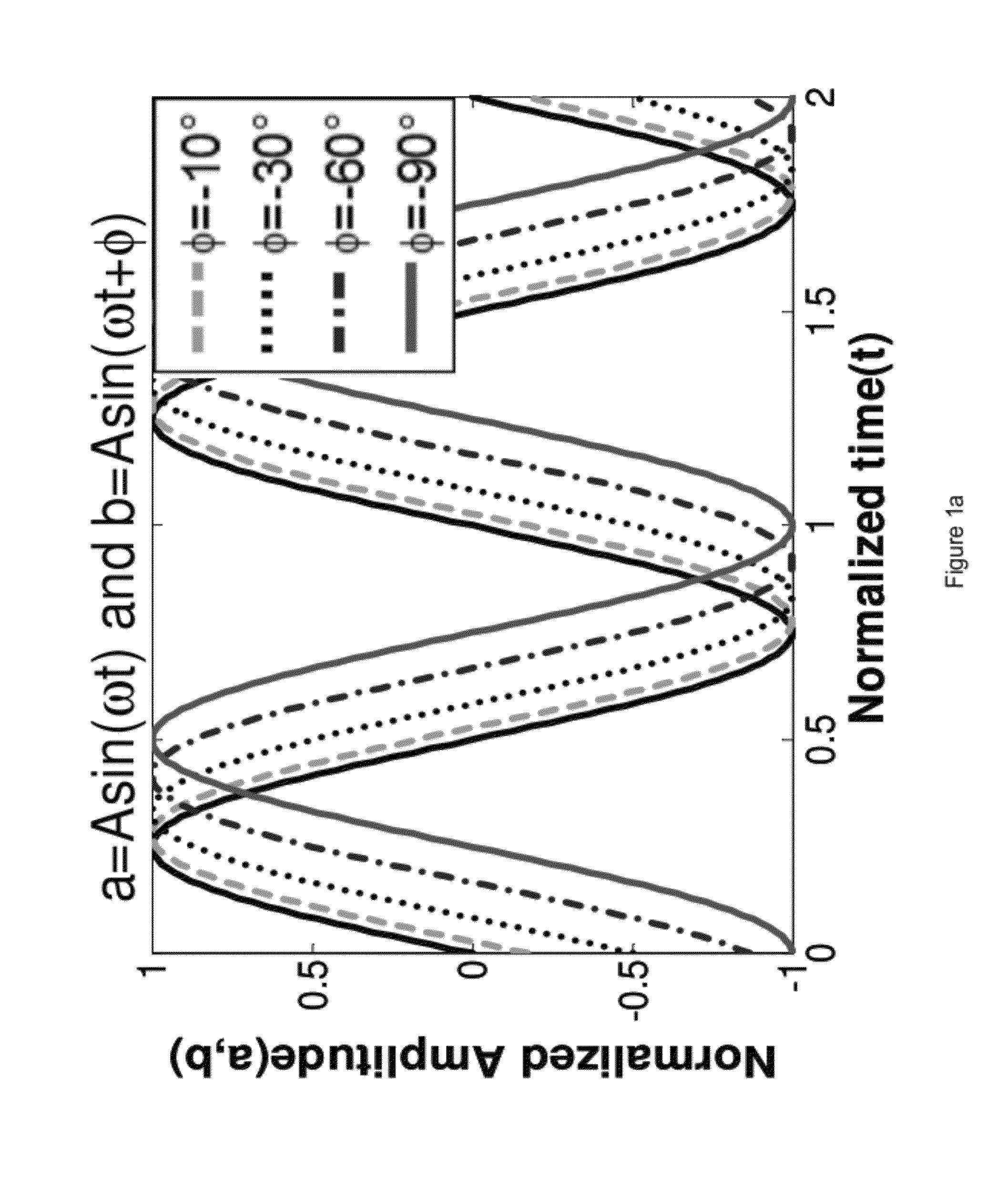
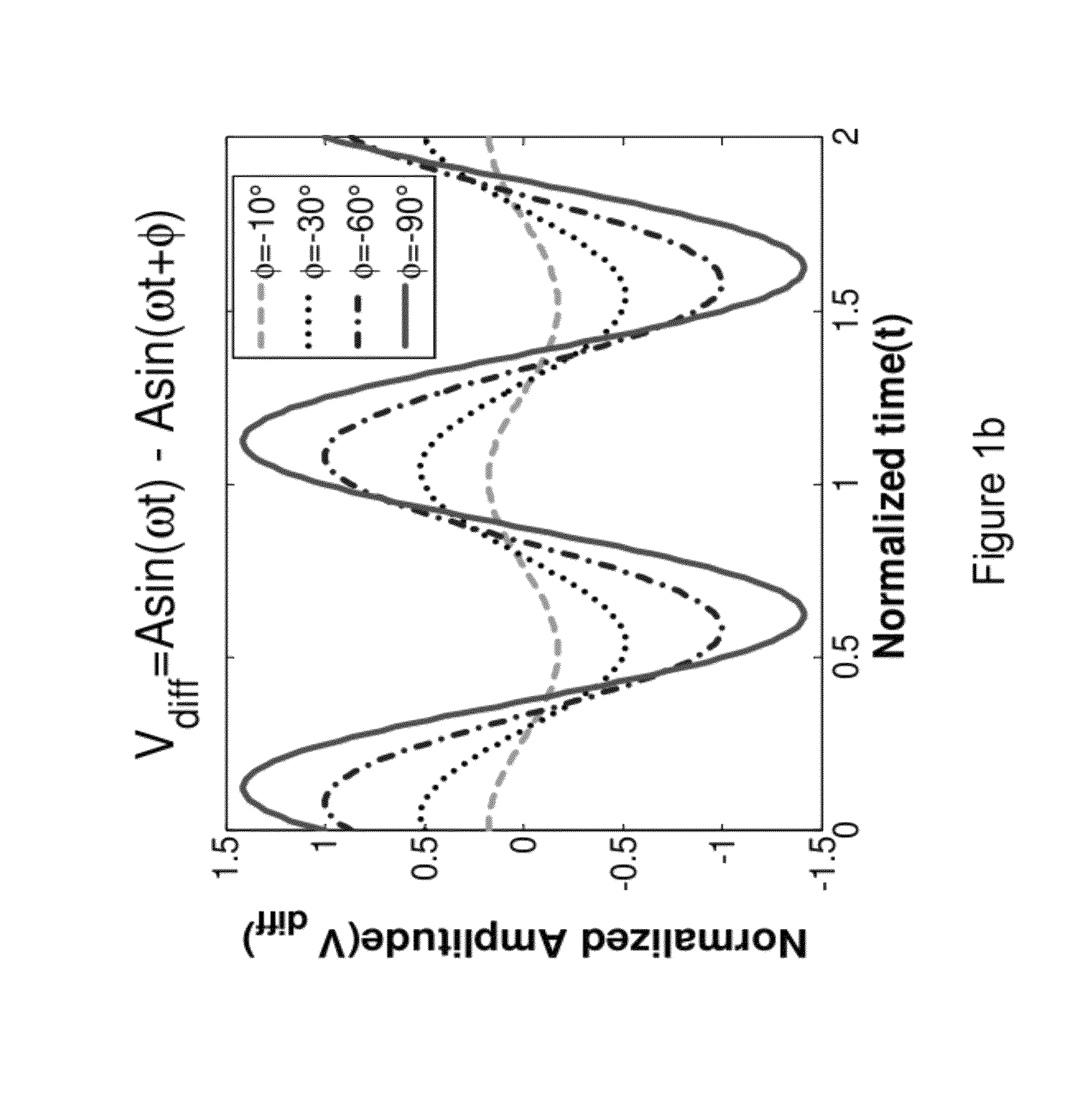
The presently invention is directed to ways to measure distortion effects while allowing for the possibility of significant reduction in test cost. An exemplary embodiment of the present invention provides a method for amplifier distortion measurement including comparing a first amplitude response of an output signal from a power amplifier to a second amplitude response of a reference input signal to determine a set of Amplitude-to-Amplitude (“AM-AM”) distortion values. Additionally, the method for amplifier distortion measurement includes equalizing the first amplitude response of the output signal to match the second amplitude response of the reference input signal based on the set of AM-AM distortion values and creating a difference signal based on a comparison of the equalized output signal to the reference input signal. Furthermore, the method for amplifier distortion measurement includes calculating a set of Amplitude-to-Phase (“AM-PM”) distortion values based on a third amplitude response of the difference signal.

Description

CROSS REFERENCE TO RELATED APPLICATION[0001]This application claims the benefit of U.S. Provisional Patent Application No. 61 / 256,547, filed 30 Oct. 2009, the entire contents and substance of which are hereby incorporated by reference as if fully set forth below.FIELD OF THE INVENTION[0002]The present invention relates generally to systems and methods for amplifier distortion measurement.BACKGROUND OF THE INVENTION[0003]The increased demand for spectrally efficient wireless communication chips necessitates the use of high linearity RF (Radio Frequency) front ends. Among other things, the high power amplifier in the transmitter is a crucial element which determines the overall linearity of the transmitted RF signal. Power Amplifiers exhibit crucial distortion effects at high power, namely amplitude and phase distortions. These are characterized as amplitude to amplitude modulation (AM-AM) and amplitude to phase modulation (AM-PM). Moreover the increasing popularity of Orthogonal Freq...

Claims


Application Information

Patent Timeline
Patent Type & Authority Patents(United States)
IPC IPC(8): H03F1/26
CPCH03F3/193
Inventor SEN, SHREYASDEVARAKOND, SHYAM KUMARCHATTERJEE, ABHIJIT
Owner GEORGIA TECH RES CORP
Learn More