
Spectrometer for identifying analyte materials

a technology of analyte materials and spectrometers, applied in the field of spectrometers, can solve the problems of alternating constructive and destructive interference between beams, conventional ftir spectrometers, such as the spectrometer described above, and suffer from a number of limitations, and conventional ftir spectrometers are sensitive to vibration and thermal effects

Inactive Publication Date: 2013-01-22
SYSTEM PLANNING CORPORATION
View PDF5 Cites 28 Cited by
  • Summary
  • Abstract
  • Description
  • Claims
  • Application Information

AI Technical Summary

Benefits of technology

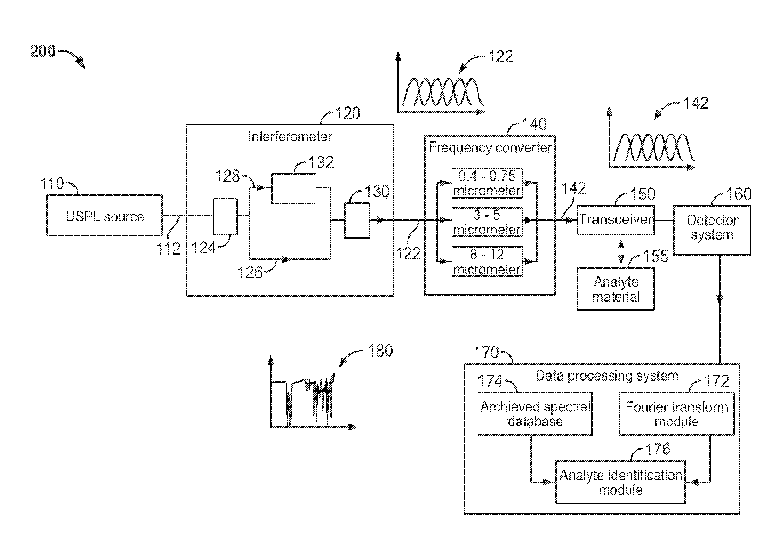
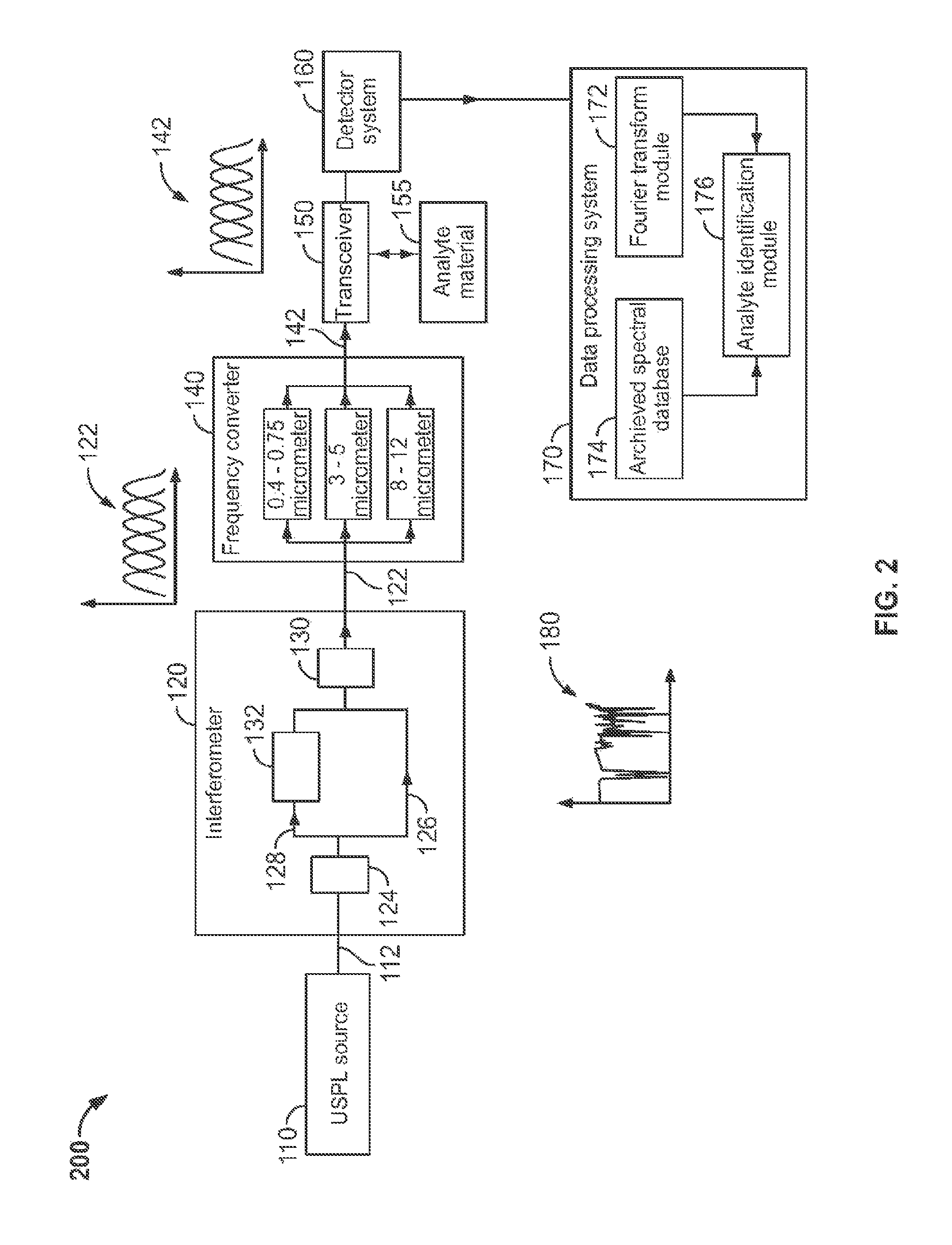
The present invention provides a spectrometer that overcomes the limitations of previous technologies. In one embodiment, the spectrometer includes a single USPL source, a fiber interferometer, a frequency converter, and transmitter / receiver optics. The USPL source generates a laser beam, which is then split by the interferometer into two beams with different lengths. The frequency converter converts the interferogram patterns generated by the interferometer to a desired wavelength band, and the transmitter optics transmit the output beam for irradiating the analyte material. The receiver optics then receive the radiation that has passed through or been reflected from the analyte material, and the data processing system transforms the radiation into a spectrum for analysis. This spectrometer has improved accuracy, precision, and speed for identifying analyte materials.

Problems solved by technology

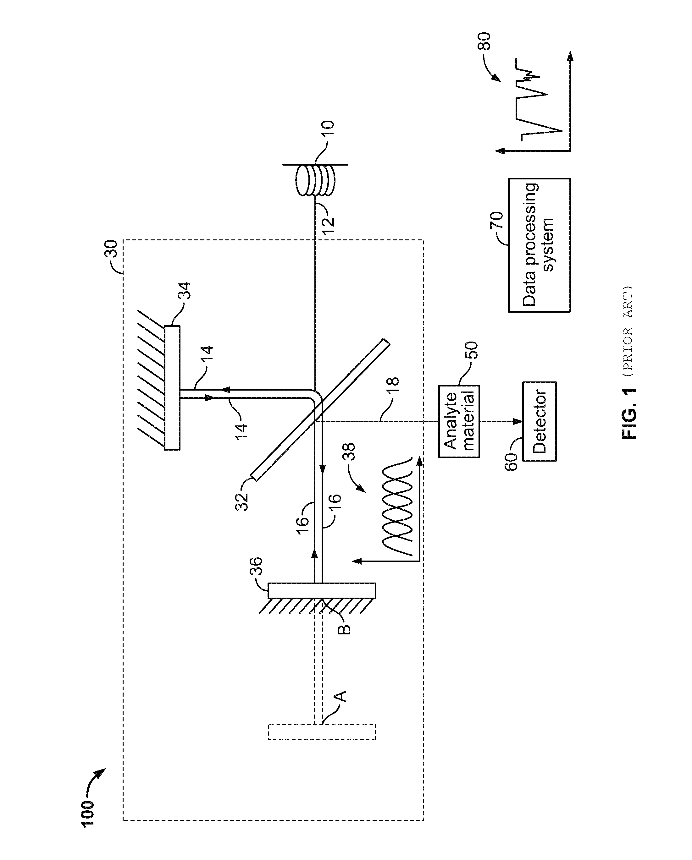
The difference in the varying path lengths of the first light beam and the second light beam results in alternating constructive and destructive interference between these beams, which is mathematically describable as a convolution of the first light beam and the second light beam.
Conventional FTIR spectrometers, such as the spectrometer described above, suffer from a number of limitations.
A major limitation is that such conventional FTIR spectrometers are sensitive to vibrations and thermal effects.
Any inaccuracy in the positioning of the moving mirror will degrade or destroy the generated spectrogram.
A further limitation of conventional FTIR spectrometers is that they are unsuitable for long-range or diffraction-limited imaging.
More specifically, incoherent light sources used in the conventional FTIR spectrometers are difficult to collimate and propagate over long distances, and cannot be focused to a diffraction-limited spot size.
Additionally, conventional FTIR spectrometers exhibit poor time resolution.
This may be attributed to physical limitations on how fast the moving mirror can be accurately translated during generation of the spectrogram.
The FTIR spectrometer taught by Van der Weide provides a well behaved beam for imaging but it requires two fragile, expensive, and inefficient solid state USPLs.
Further, this type of FTIR spectrometer requires complicated locking electronics to precisely synchronize the repetition rates of the two USPLs.

Method used


Image

  • Spectrometer for identifying analyte materials
  • Spectrometer for identifying analyte materials
  • Spectrometer for identifying analyte materials

Examples


Embodiment Construction

[0032]The present invention will be described in detail with reference to the accompanying drawings. Throughout the present description, it should be understood that the term ‘spectrometer’ as mentioned herein refers to an instrument that analyzes radiation patterns of analyte materials. Further, herein the term ‘identifying’ the analyte material refers to detecting, characterizing, quantifying, or imaging the analyte material. Further, it should be understood that the ‘analyte material’ as mentioned herein refers to any chemical substance, or object that may be required to be detected, imaged, identified, and / or characterized by the spectrometer. For example, the analyte material may include hazardous airborne, waterborne, and / or surface-adhered biological and chemical species (including explosives residues), concealed or buried objects, or facilities suspected to contain chemical or biological species of interest.

[0033]FIG. 2 is a block diagram of a spectrometer 200 according to a...


PUM


Abstract

A spectrometer for identifying an analyte material. One embodiment of the spectrometer includes a single ultrashort pulsed laser (USPL) source, a fiber interferometer, a frequency converter and a transceiver. The USPL source is configured to generate a laser beam. The interferometer is operatively coupled to the USPL source, and is configured to split the laser beam into a first laser beam and a second laser beam, providing a variable difference in lengths between the paths of the first laser beam and the second laser beam. The spectrometer then electronically scans the variable-path second laser beam over the first laser beam to generate interferogram patterns. The frequency converter is configured to receive the interferogram patterns from the interferometer, and perform a frequency conversion of the interferogram patterns to form an output beam. The transceiver is configured to transmit the output beam and to receive radiation from the analyte material. The radiation is thereafter used to identify the analyte material.

Description

CROSS REFERENCE TO RELATED APPLICATIONS[0001]None.BACKGROUND[0002]1. Technical Field[0003]The present invention relates to spectrometers for identifying analyte materials and more particularly, to a Fourier transform based spectrometer.[0004]2. Description of Related Art[0005]Spectrometers are generally utilized in detecting, characterizing, quantifying, or imaging analyte materials. Such analyte materials may be any chemical substance or object detected, characterized, quantified, or imaged by the spectrometer. For example, the analyte material may include airborne, waterborne and / or surface-adhered chemical species, concealed or buried objects, or facilities suspected to contain chemical or biological species of interest.[0006]One type of conventional spectrometer technology known in the art is the Fourier Transform Infrared (FTIR) Spectrometer. FIG. 1 is a schematic diagram of an FTIR spectrometer known in the art. This type of FTIR spectrometer 100 generally includes an incohere...

Claims


Application Information

Patent Timeline
Patent Type & Authority Patents(United States)
IPC IPC(8): G01B9/02
CPCG01J3/36G01J3/45
Inventor DEWITT, KRISTIN MARIEDEWITT, MERRICK JOSEPH
Owner SYSTEM PLANNING CORPORATION
Learn More