Method for adjusting boost pressure while regenerating a particulate filter for a direct injection engine

a technology of boost pressure and direct injection engine, which is applied in the direction of electric control, machines/engines, mechanical equipment, etc., can solve the problems of short opportunity for injected fuel to completely fill and particles may form in engine exhaust, so as to reduce engine pumping losses, reduce engine fuel economy, and reduce internal combustion engine emissions

Active Publication Date: 2013-01-29
FORD GLOBAL TECH LLC
View PDF33 Cites 10 Cited by
  • Summary
  • Abstract
  • Description
  • Claims
  • Application Information

AI Technical Summary

Benefits of technology

[0003]Exhaust gas recirculation (EGR) has been used to lower emissions of internal combustion engines. Introducing EGR to engine cylinders can reduce engine pumping losses as well as formation of NOx. In WO2008 / 127755, a system is described having an EGR passage located downstream of a compressor on the intake side of an engine and upstream of a turbine on the exhaust side of the engine. The reference also describes a catalyst and particulate filter disposed in the exhaust system at a location downstream of the turbine. In one configuration, the reference describes flowing gases from a location downstream of the compressor at the intake side of the engine, to a location in the exhaust system upstream of the catalyst and particulate filter. Further, the reference describes adjusting the boost pressure when the pressure in the exhaust manifold is higher than the pressure in the intake manifold. The method may help to ensure flow from the intake manifold to the exhaust system, but the compressor may be operated such that the flow from the intake system to the exhaust system is low. Alternatively, the compressor may be operated such that a higher pressure than is desired such that engine fuel economy is reduced.
[0004]Recently, direct injection gasoline engines have been shown to improve engine performance and to reduce transient air-fuel disturbances that may be caused by fuel adhering to the intake manifold and ports of an engine. However, at higher engine speeds and higher engine loads, particulates may form in engine exhaust. Under some conditions, formation of the particulates may be related to the short amount of time between when fuel is injected to the cylinder and when combustion is initiated by a spark plug. Specifically, there may be only a short opportunity for the injected fuel to completely vaporize and form a homogeneous mixture before combustion is initiated. If a homogeneous air-fuel mixture is not formed in the cylinder before combustion is initiated, pockets of stratification may form, and soot may be produced by combusting rich areas within the cylinder air-fuel mixture. Particulate filters have been proposed as one way to reduce emissions of soot.
[0006]By adjusting boost pressure in response to at least a state of particulate filter regeneration, boost pressure may be controlled such that there is sufficient flow between an intake system and an exhaust system without producing a shortage or excess of boost. In this way, a particulate filter may be regenerated with intake system gases without over or under boosting the engine. Further, the compressor boost pressure can be adjusted as the particulate filter regenerates to allow for changes in the rate of oxidation of material held by the filter so that matter held by the particulate filter is oxidized efficiently.
[0007]The present description may provide several advantages. Specifically, the approach may improve engine emissions by allowing a catalyst to operate in an efficient operating window while at the same time regenerating a particulate filter. Further, the present method allows boost to be adjusted such that under boost and over boost are reduced. Further still, the rate of particulate matter oxidation can be regulated by controlling the flow between the intake system and the exhaust system from feedback output from an oxygen sensor located downstream of the particulate filter and at least partially sensing oxidation of material held by the particulate filter.

Problems solved by technology

However, at higher engine speeds and higher engine loads, particulates may form in engine exhaust.
Specifically, there may be only a short opportunity for the injected fuel to completely vaporize and form a homogeneous mixture before combustion is initiated.

Method used


Image

  • Method for adjusting boost pressure while regenerating a particulate filter for a direct injection engine
  • Method for adjusting boost pressure while regenerating a particulate filter for a direct injection engine
  • Method for adjusting boost pressure while regenerating a particulate filter for a direct injection engine

Examples


Embodiment Construction

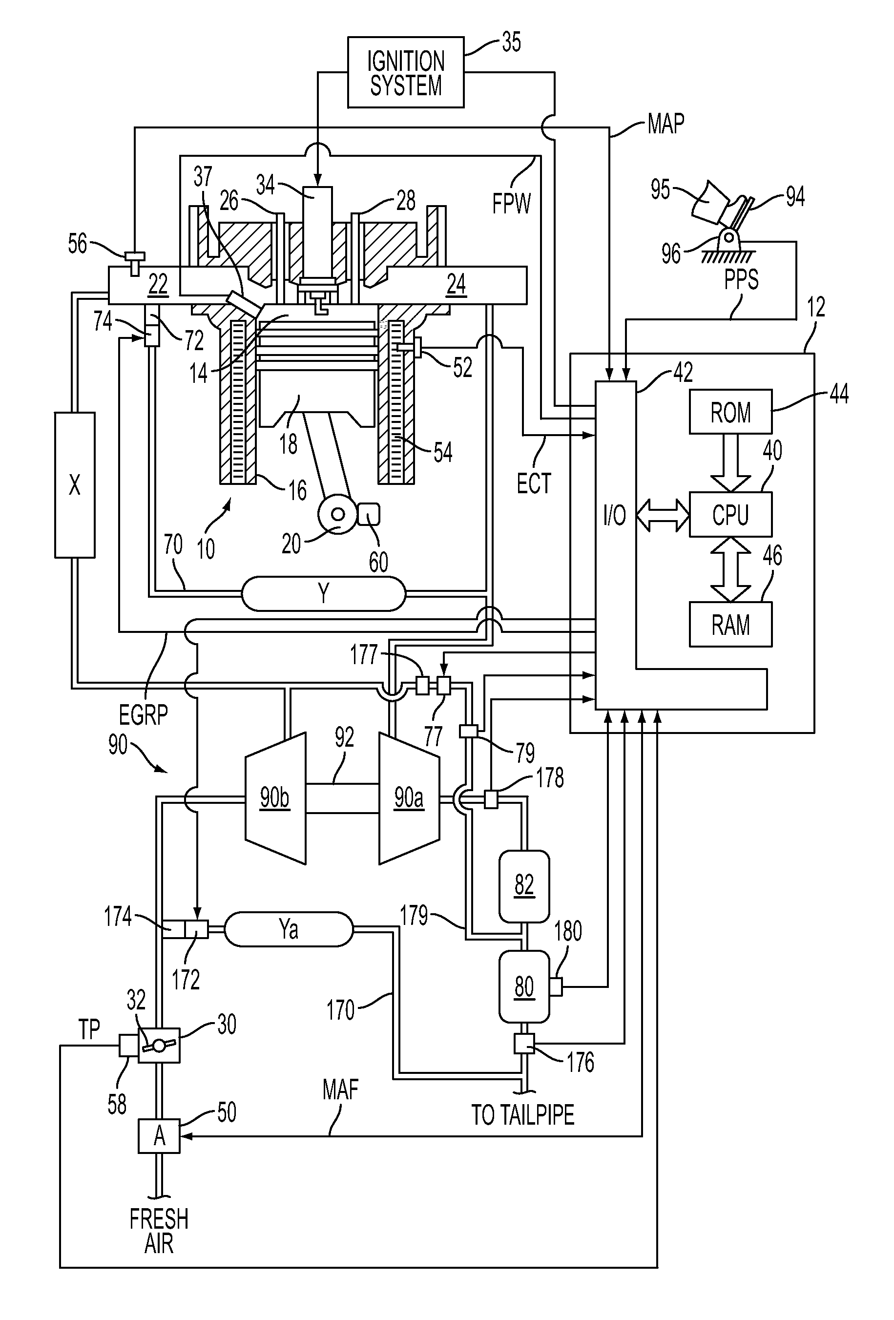
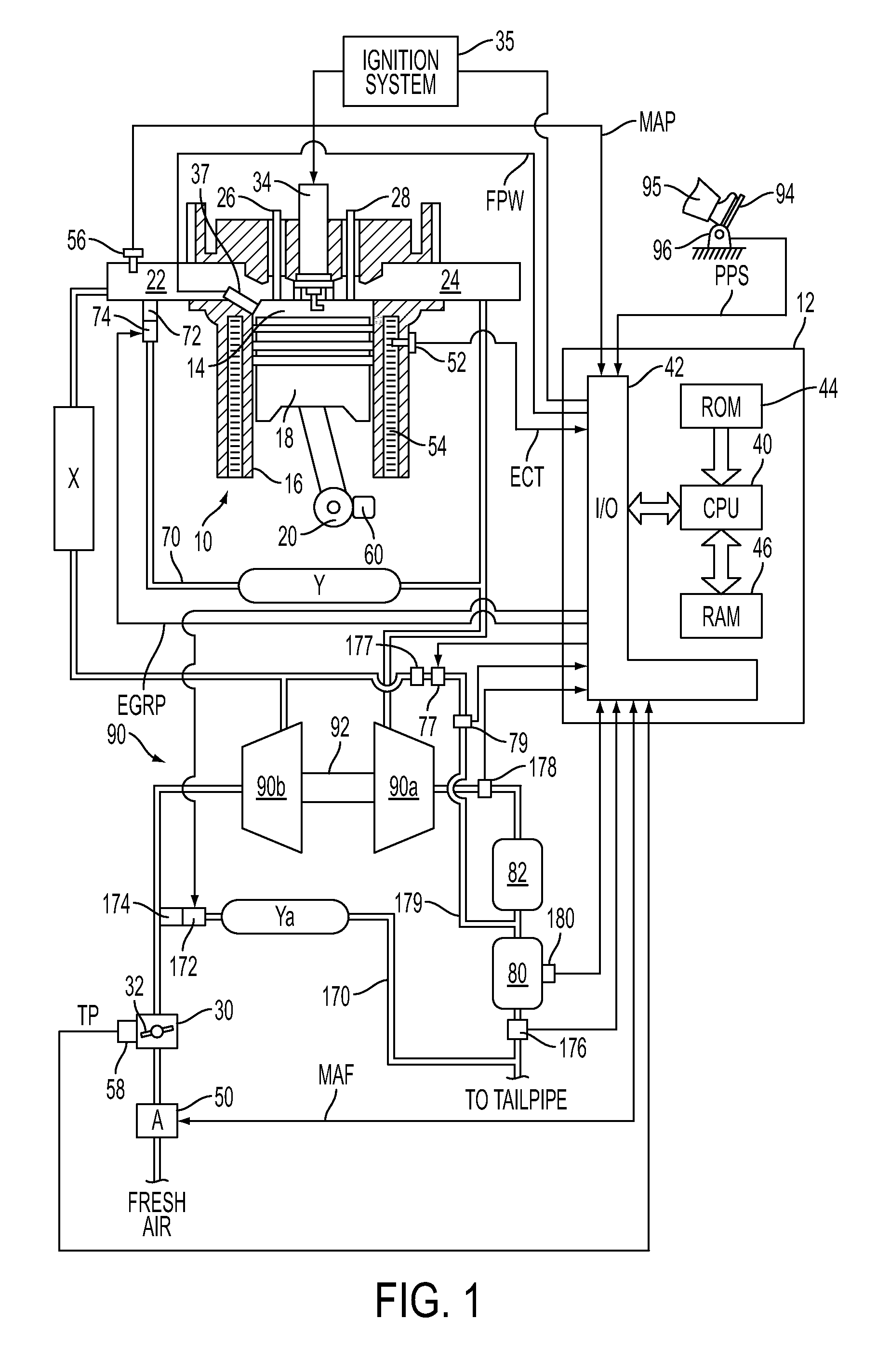
[0015]FIG. 1 shows an exemplary embodiment of a gasoline direct injection engine system generally at 10. Specifically, internal combustion engine 10 comprises a plurality of cylinders, one cylinder of which is shown in FIG. 1. Engine 10 is controlled by electronic engine controller 12. Engine 10 includes combustion chamber 14 and cylinder walls 16 with piston 18 positioned therein and connected to crankshaft 20. Combustion chamber 14 communicates with an intake manifold 22 and an exhaust manifold 24 via respective intake valve 26 and exhaust valve 28.

[0016]Intake manifold 22 communicates with throttle body 30 via throttle plate 32. In one embodiment, an electronically controlled throttle can be used. In one embodiment, the throttle is electronically controlled to periodically, or continuously, maintain a specified vacuum level in intake manifold 22. Note that throttle body 30 and throttle plate 32 may be located at a location downstream of compression device 90 in some applications....


PUM


Abstract

A method for regenerating a particulate filter is disclosed. In one example, oxygen is pumped from the intake system of a direct injection turbocharged gasoline engine to the exhaust system by a compressor. The oxygen is introduced to a particulate filter at a location upstream from the particulate filter and downstream of a three-way catalyst. The oxygen may be regulated in part by adjusting compressor boost pressure in response to a state of particulate filter regeneration. Further, in one embodiment, engine NOx can be controlled by EGR.

Description

CROSS-REFERENCE TO RELATED APPLICATIONS[0001]This application claims priority from U.S. Provisional Patent Application No. 61 / 246,926, entitled “SYSTEM AND METHOD FOR REGENERATING A PARTICULATE FILTER FOR A DIRECT INJECTION ENGINE”, filed Sep. 29, 2009, the disclosure of which is hereby incorporated by reference in its entirety and for all purposes.TECHNICAL FIELD[0002]The present application relates to the field of automotive emission control systems and methods.BACKGROUND AND SUMMARY[0003]Exhaust gas recirculation (EGR) has been used to lower emissions of internal combustion engines. Introducing EGR to engine cylinders can reduce engine pumping losses as well as formation of NOx. In WO2008 / 127755, a system is described having an EGR passage located downstream of a compressor on the intake side of an engine and upstream of a turbine on the exhaust side of the engine. The reference also describes a catalyst and particulate filter disposed in the exhaust system at a location downstre...

Claims


Application Information

Patent Timeline
Patent Type & Authority Patents(United States)
IPC IPC(8): F01N3/22
CPCF01N3/0231F01N3/101F01N3/30F02B37/00F01N13/009F02D41/029F01N2410/04F02D2250/41Y02T10/144F02D41/0007Y02T10/22F02D41/0055Y02T10/12
Inventor VAN NIEUWSTADT, MICHIEL J.RUHLAND, HELMUT HANSSPRINGER, MORITZ KLAUSLORENZ, THOMASLOUVEN, GEORGHARMSEN, JAN
Owner FORD GLOBAL TECH LLC
Why Eureka
Try Eureka