
Architecturally advanced air handling unit

Active Publication Date: 2013-01-29
SEMMES THOMAS MIDDLETON
View PDF14 Cites 29 Cited by
  • Summary
  • Abstract
  • Description
  • Claims
  • Application Information

AI Technical Summary

Benefits of technology

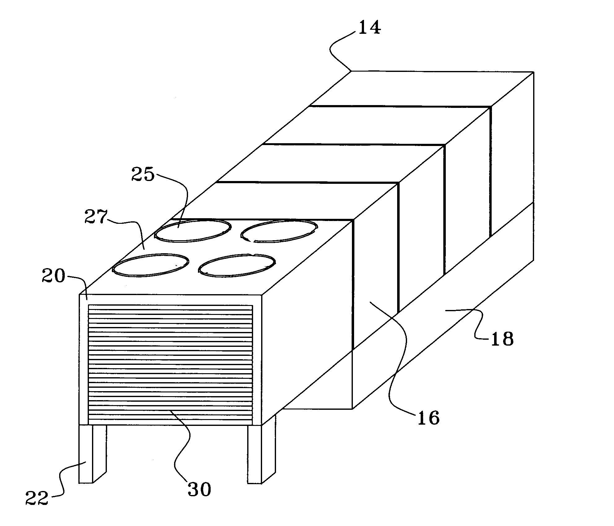
The present invention provides an improved design for an AHU that can be easily disguised, modular, efficient, and easy to service. It also reduces emissions of noise and allows for direct placement of additional AHU's. Additionally, the design has minimal side accesses and protrusions, and aims to reduce noise levels.

Problems solved by technology

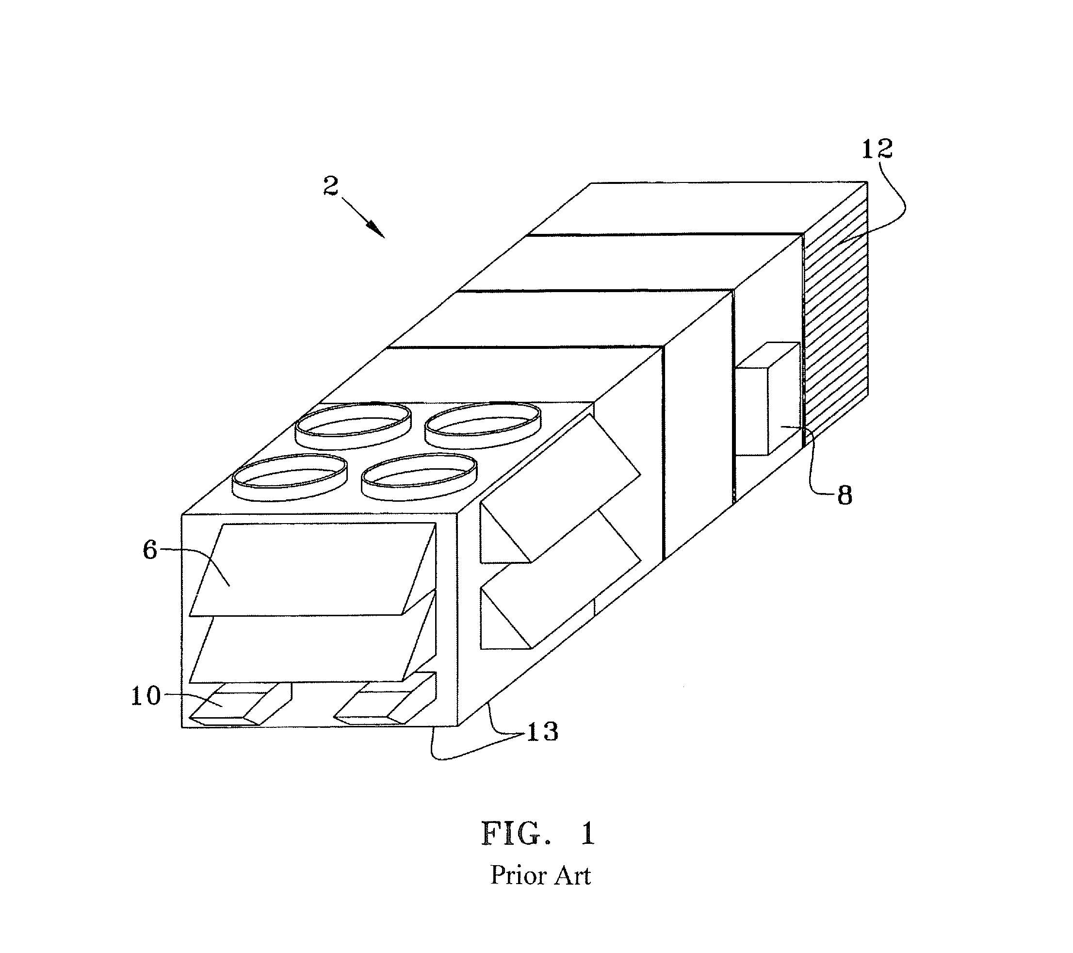
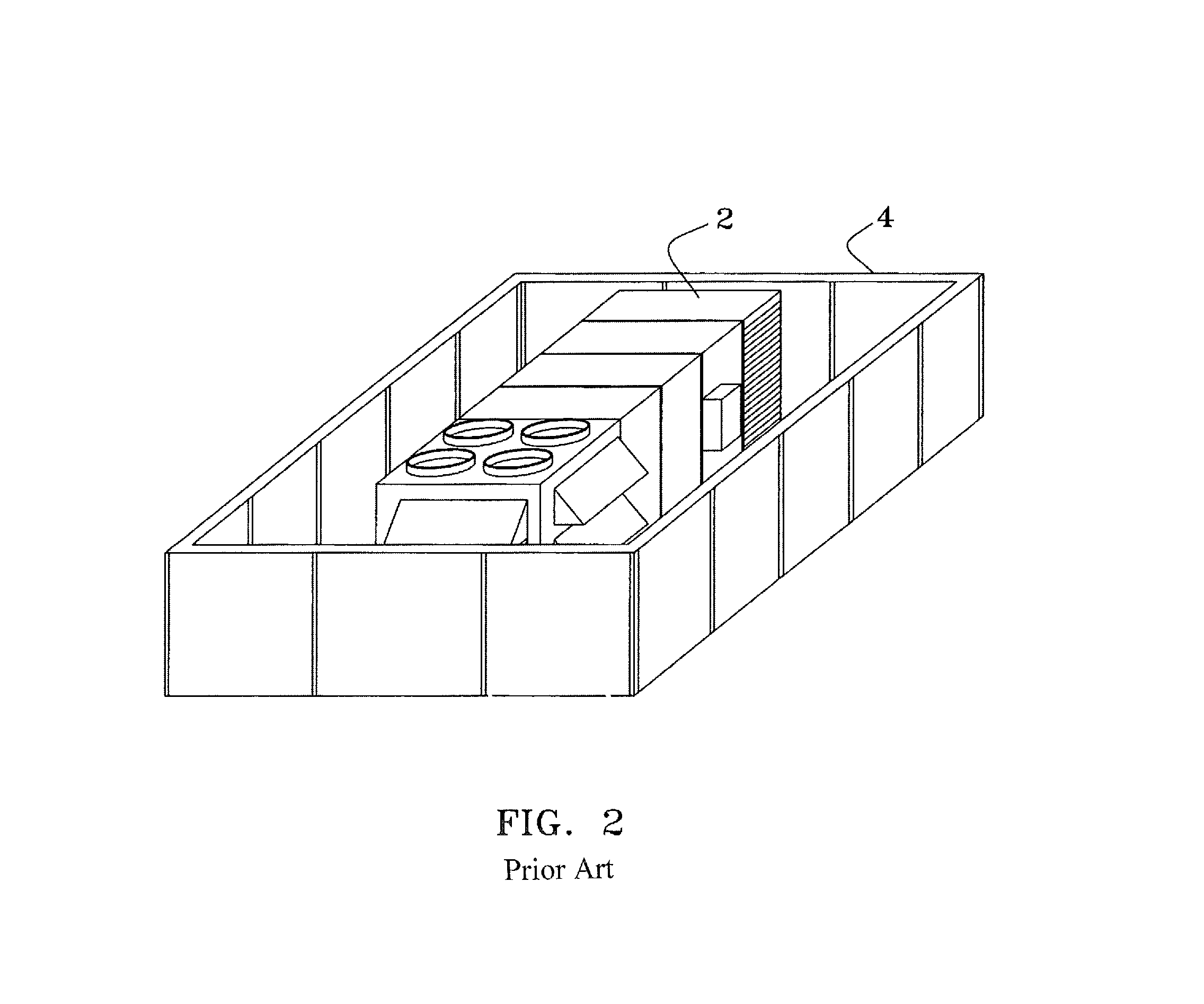
These units being noisy, large and requiring a moderate amount of access space, are generally located on the rooftop, or on ground level, about the perimeter of the building.
Herein lies part of the problem with the prior art.

Method used


Image

  • Architecturally advanced air handling unit
  • Architecturally advanced air handling unit
  • Architecturally advanced air handling unit

Examples


second embodiment

[0039]FIGS. 10 and 11 illustrate top cross sectional and side cross sectional views of an alternate embodiment IAHU 78 with a refrigerant based heat recovery system. Here it can be seen that additional slant filters 42 and slant cooling coils 44 have been added above the outside air damper 36 to allow additional cooling and filtration capacity of the air while not increasing the outside dimensions of the second embodiment IAHU 78 over those of the preferred embodiment IAHU 14. The air conditioning components 48 reside over an extended lower base 18 and share a common heat rejection room 52 with the slant heat exchangers 66. The floor 80 beneath the slant heat exchangers may be open to allow additional rooftop fans 25 draw outside air into heat rejection room 52 up through the open floor 80 and across slant heat exchangers 66 as indicated by indication arrows 82 and 84. The proximate end wall 26 may be louvered. Note that depending upon the specific components installed in the AHU th...

third embodiment

[0040]FIGS. 12 and 13 illustrate top cross sectional and side cross sectional views of a third embodiment IAHU 86 with full outside air supply and a heat pump. This embodiment does not condition and return any of the building air but rather continually intakes fresh air (as indicated by direction arrow 90) and conditions it through slant filters 42 and slant cooling coils 44 for cycling through the building (as indicated by direction arrow 92) and then out of the building as exhaust air via heat rejection room 52 and roof fans 25 as indicated by direction arrows 94 and 96. As such, this embodiment does not have a plenum 38 but rather just an intake room 39. Again the prime mover is supply air fans 46 which reside in fan room 45 and draw the outside air through the distal louvered end wall 34 and pushes it, once conditioned, into the building through ducting in the lower unit 18. The floor 80 beneath the slant heat exchangers 66 maybe open to the rooftop fans 25 to draw outside air i...


PUM


Abstract

The present invention is an improved AHU that can be easily architecturally disguised, made in a modular unit, have increased overall efficiency and ease of servicing, reduce radial noise emissions and allow for the direct adjacent placement of additional AHU's. This AHU has a cuboid structure with smooth side walls that are insulated and adapted for the attachment of aesthetic surface treatments, roof inset fans louvered end walls with door access. Heat removal can accomplished through angled heat exchangers also housed within the enclosure. Air filtration is also accomplished with angled filters. The improved aesthetic appearance of these units also eliminates the use of surrounding architectural parapet walls or screening units. The improved space effectiveness and modularity shall provide greater flexibility in building construction.

Description

BACKGROUND OF THE INVENTION[0001]The present invention relates to an architecturally advanced and more space efficient design for air handling units with or without an accompanying heat rejection unit.[0002]Large capacity air handling units are a necessity for most large buildings whether residential, commercial or industrial in nature. These units being noisy, large and requiring a moderate amount of access space, are generally located on the rooftop, or on ground level, about the perimeter of the building. Herein lies part of the problem with the prior art. These packaged outdoor units are in visible locations yet form architectural eyesores. To remedy this situation, architects go to great lengths to make aesthetically appealing disguises. Walls, fences and flora are used to hide ground units whereas parapet wails and screening are used on roof units.[0003]Where more than a single air handling unit (AHU) is required, additional units are generally located near rather than adjacen...

Claims


Application Information

Patent Timeline
IPC IPC(8): F24F7/02
CPCF24F13/20F24F13/24F24F3/044F24F2221/26F24F2221/36
Inventor SEMMES, THOMAS MIDDLETON
Owner SEMMES THOMAS MIDDLETON
Learn More