Charged particle beam exposure system and beam manipulating arrangement

a beam exposure system and charge technology, applied in the field of charged particle beam exposure system and beam manipulating arrangement, can solve the problems of inhomogeneous deformation or bulging, distorted pattern of the arrangement of the plurality of apertures, and rise of the temperature of the central portion of the multi-aperture pla

Active Publication Date: 2013-02-05
CARL ZEISS SMT GMBH
View PDF20 Cites 10 Cited by
  • Summary
  • Abstract
  • Description
  • Claims
  • Application Information

AI Technical Summary

Benefits of technology

[0020]According to a further exemplary embodiment, the beam manipulating arrangement comprises at least one heat sink having an inner heat receiving surface surrounding at least one of the beam or beams incident on the protective plate, and the beams having traversed the deflector plate. Such heat sink allows for a radiation cooling of the central portions of the respective plates such that a temperature gradient between the central portion and the frame portion is reduced.
[0022]According to an exemplary embodiment herein, the inner surface of the heat sink facing towards the central portion has a higher thermal emissivity than a surface of the heat sink facing towards the heater. This may avoid an undesired heat transfer between the heater and the heat sink.
[0025]The deflector plate has regions where the number of apertures per unit area is higher than in other regions. Further, the number of circuit device elements for controlling the deflectors associated with the apertures may vary between different regions of the central portion of the deflector plate. It is apparent that a heat per unit area of the central portion generated by the operation of the circuit device elements or by charged particles incident on the substrate material defining the apertures will vary across the area of the central portion of the deflector plate. There will be regions where an amount of heat introduced into the substrate material of the central portion is higher than in other regions. In view of reducing temperature gradients across the central portion, a radiation cooling mechanism of the central portion is designed such that heat is more effectively carried away from regions where more heat is generated than in regions where the heat generated per unit area is lower. This is achieved by varying a heat emissivity of a surface of the central portion of the deflector plate from region to region. This may be further achieved by varying a heat emissivity of a surface of the protective plate facing towards the deflector plate.
[0029]The balls allow to maintain a position of the plates relative to each other by providing a well-defined mechanical contact between the plates. Further, the balls allow for a thermal expansion of one plate relative to the other without generating tensile or compressive stresses between the plates. Further, a transfer of heat from one plate to the other by heat conduction is relatively low due to the small contact area between the balls and the plates.

Problems solved by technology

The beam or beams incident on the multi-aperture plate and the operation of the electronic circuitry controlling the deflectors generate heat resulting in a rise of temperature of the central portion of the multi-aperture plate during operation of the beam manipulating arrangement.
Such changes of internal stress might result in an inhomogeneous deformation or bulging of the central portion and, thus, in a distorted pattern of the arrangement of the plurality of apertures.

Method used


Image

  • Charged particle beam exposure system and beam manipulating arrangement
  • Charged particle beam exposure system and beam manipulating arrangement
  • Charged particle beam exposure system and beam manipulating arrangement

Examples


Embodiment Construction

[0039]In the exemplary embodiments described below, components that are alike in function and structure are designated as far as possible by alike reference numerals. Therefore, to understand the features of the individual components of a specific embodiment, the descriptions of other embodiments and of the summary of the invention should be referred to.

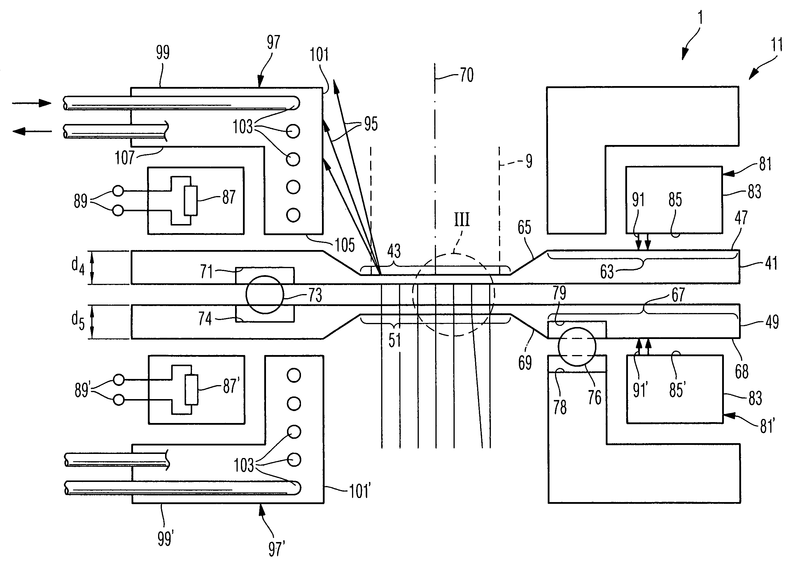
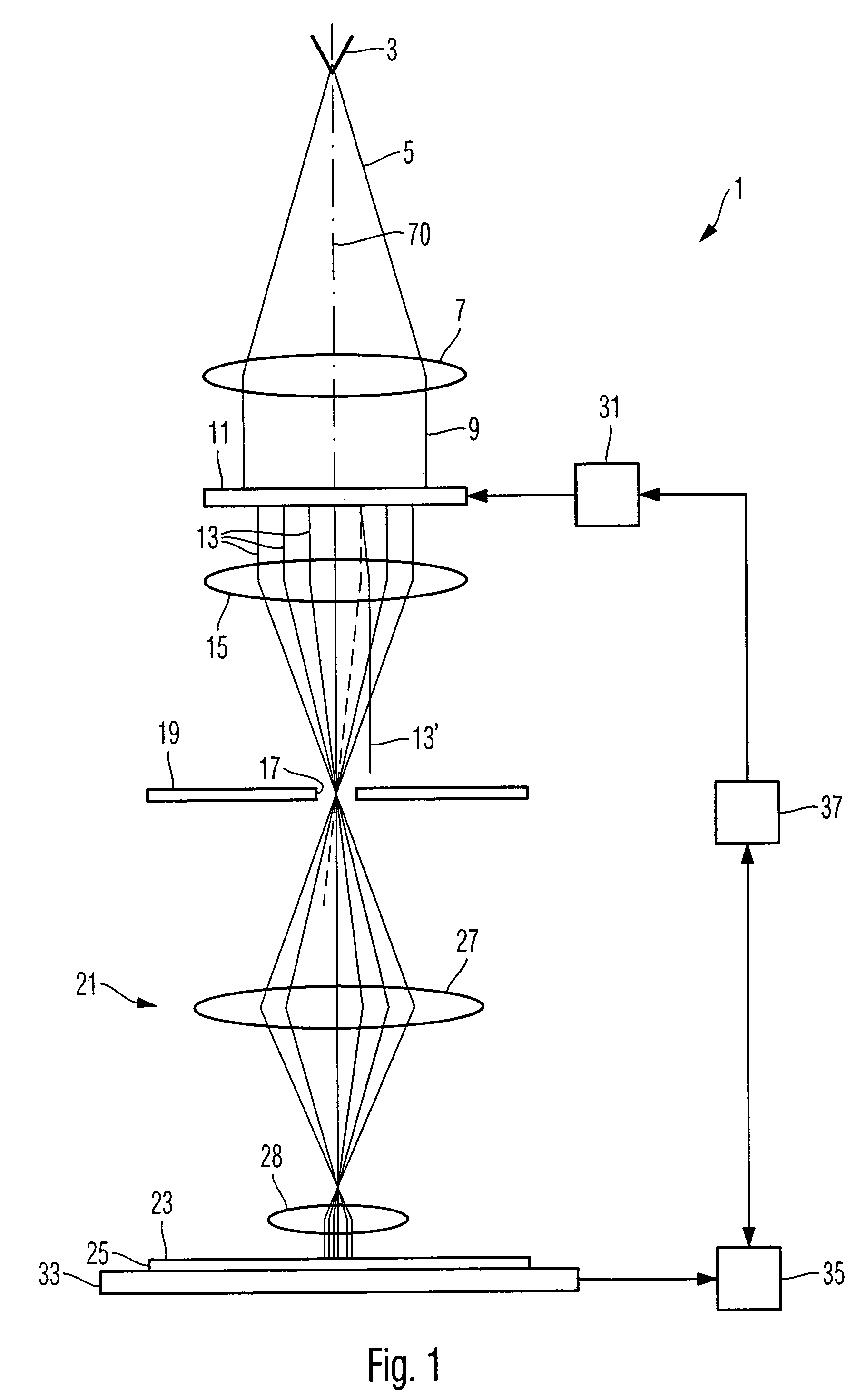
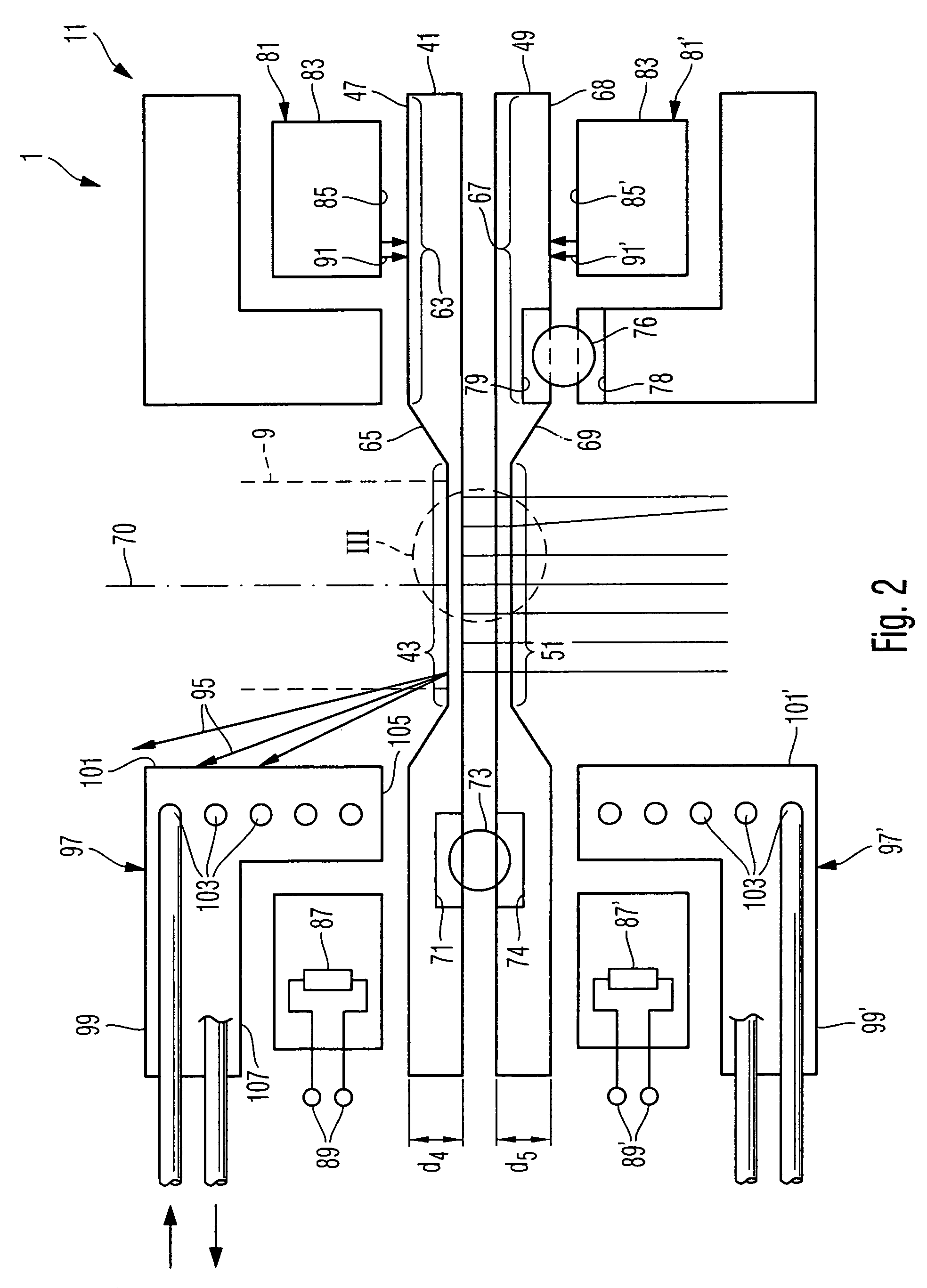
[0040]FIG. 1 illustrates a charged particle beam exposure system using a plurality of electron beams for exposing a pattern onto a substrate, such as a semiconductor wafer.

[0041]The system uses a deflector plate having a plurality of apertures and deflectors associated therewith for individually controlling the plurality of beams. Background information on such types of exposure systems and in particular methods of operations thereof and manufacturing of multi-aperture plates incorporated therein may be obtained from US 2003 / 0025088 A1, U.S. Pat. No. 5,262,341, U.S. Pat. No. 5,814,423 and U.S. Pat. No. 6,465,796 B1, the contents of w...


PUM


Abstract

A beam manipulating arrangement for a multi beam application using charged particles comprises a multi-aperture plate having plural apertures traversed by beams of charged particles. A frame portion of the multi-aperture plate is heated to reduce temperature gradients within the multi-aperture plate. Further, a heat emissivity of a surface of the multi-aperture plate may be higher in some regions as compared to other regions in view of also reducing temperature gradients.

Description

CROSS REFERENCE TO RELATED APPLICATION[0001]This application is the National Phase application of International Application No. PCT / EP2006 / 007182, filed Jul. 20, 2006, which designates the United States and was published in English. This application, in its entirety, is incorporated herein by reference.BACKGROUND OF THE INVENTION[0002]1. Field of the Invention[0003]The present invention relates to a charged particle beam exposure system used, for example, in a lithographic method, and a beam manipulating arrangement for manipulating a plurality of charged particle beams.[0004]2. Brief Description of Related Art[0005]Lithographic processes are commonly used in the manufacture of miniaturized structures, such as semiconductor elements, integrated circuits, liquid crystal elements, micro-patterned members and micro-mechanical components.[0006]A lithographic process comprises a plurality of lithographic steps in which patterns or structures to be formed on a substrate are imaged onto th...

Claims


Application Information

Patent Timeline
Patent Type & Authority Patents(United States)
IPC IPC(8): G21K5/04
CPCB82Y10/00H01J37/3174B82Y40/00H01J2237/0435H01J37/317H01J37/36
Inventor PLATZGUMMER, ELMARSTENGL, GERHARD
Owner CARL ZEISS SMT GMBH
Why Eureka
Try Eureka