Aircraft bird strike avoidance method and apparatus using axial beam antennas

a technology of axial beam and avoidance method, which is applied in the direction of waveguide horns, non-resonant long antennas, instruments, etc., can solve the problem of difficult mounting position of long aperture antennas, and achieve the effect of improving low speed performan

Inactive Publication Date: 2013-02-05
PIESINGER GREGORY HUBERT
View PDF17 Cites 8 Cited by
  • Summary
  • Abstract
  • Description
  • Claims
  • Application Information

AI Technical Summary

Benefits of technology

[0012]In the present invention, an end-fire monopole array is implemented in the form of a stall fence. Stall fences are used on a variety of aircraft to improve low speed performance.

Problems solved by technology

Unfortunately, these surfaces can be covered with deicing boots thus making it a difficult position to mount long aperture antennas.

Method used


Image

  • Aircraft bird strike avoidance method and apparatus using axial beam antennas
  • Aircraft bird strike avoidance method and apparatus using axial beam antennas
  • Aircraft bird strike avoidance method and apparatus using axial beam antennas

Examples


Embodiment Construction

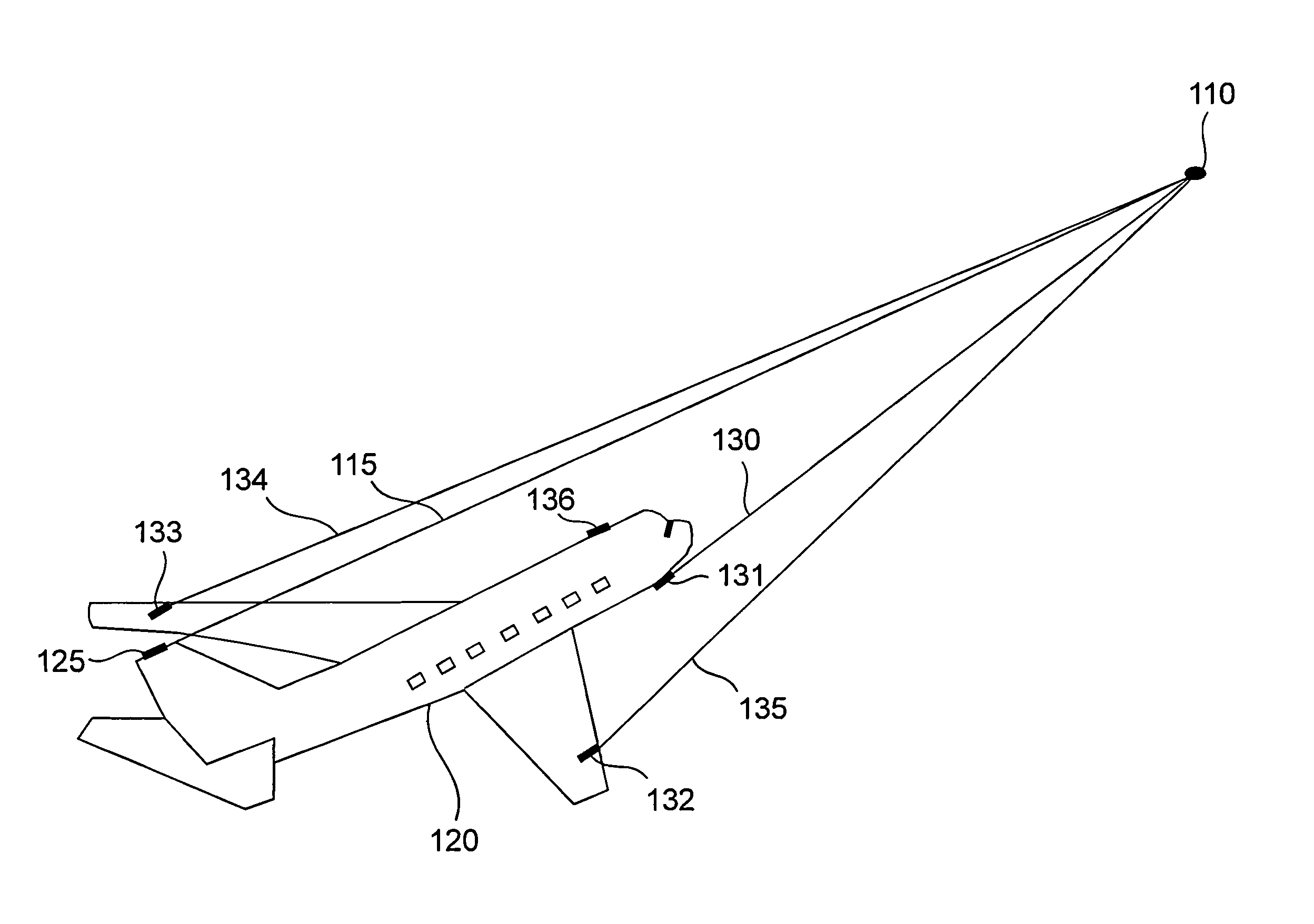
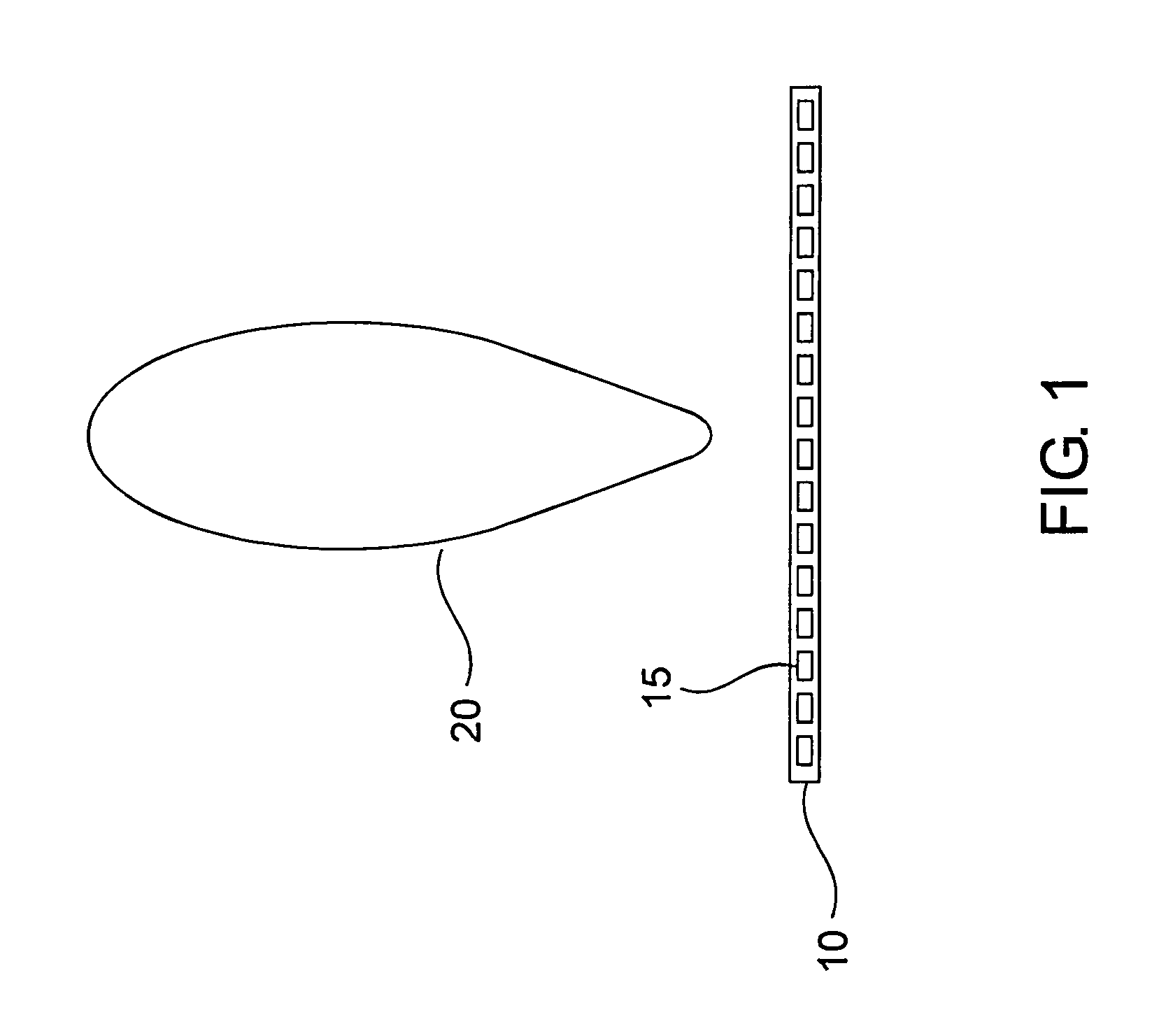
[0024]FIG. 1 illustrates a long narrow slotted array antenna 10 composed of array aperture elements 15 that produces broadside antenna pattern 20. In the previously referenced patent applications, the mounting of this antenna was illustrated on the leading edge of the wings, tail, and on the top forward area of the fuselage.

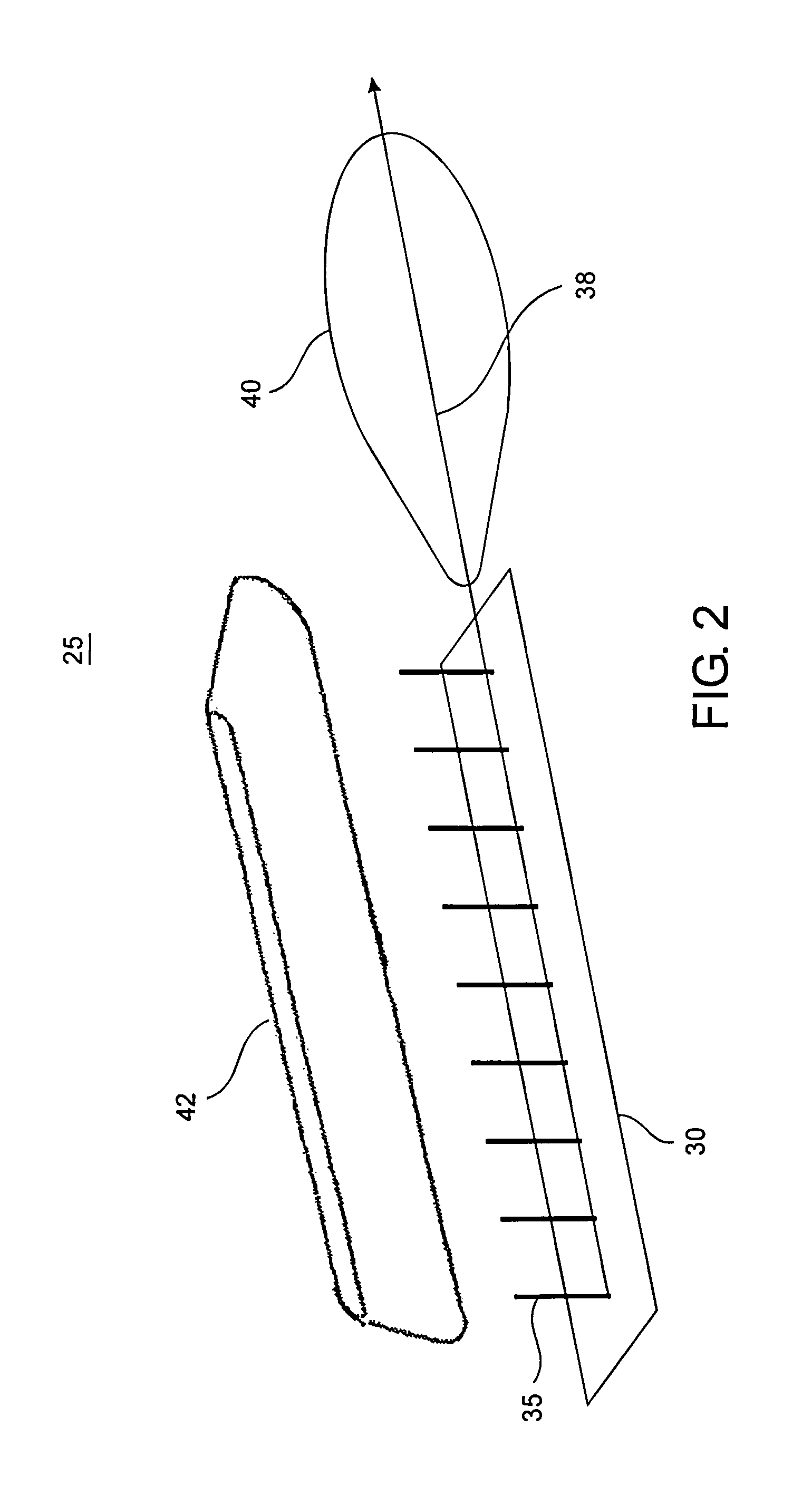
[0025]An end-fire array 30 of monopole antenna elements 35 can be constructed as illustrated in FIG. 2. As is well known by those skilled in the art, maximum radiation occurs in the axial direction 38 producing antenna pattern 40. In the current invention, this end-fire array is enclosed in housing 42 and mounted on an aircraft surface similar to the way stall fence 45 is mounted on wing 50 in FIG. 3. Stall fence antenna 25 allows a narrow antenna beamwidth to be obtained in the forward direction without having to mount a long narrow antenna along a forward facing surface of the aircraft.

[0026]The primary feature of stall fence antenna 25 is that forward directiv...


PUM


Abstract

An aircraft avian radar is implemented using multiple axial beam antennas mounted on an aircraft. Target range is determined by radar range. Target azimuth and elevation position is determined by triangulation. An end-fire array antenna composed of a series of monopole antenna elements enclosed inside a long thin protective cover fashioned in the form of a stall fence is mounted on the wings, tail, or fuselage to produce a low drag axial beam antenna pattern directed ahead of the aircraft. Other axial beam antenna choices include helical, pyramidal horn, and conical horn antennas mounted on or inside various forward facing surfaces of the aircraft.

Description

RELATED INVENTION[0001]The present invention claims priority under 35 U.S.C. §119(e) to: “Aircraft Bird Strike Avoidance Method and apparatus using Axial beam Antennas” Provisional U.S. Patent Application Ser. No. 61 / 268,955, filed 18 Jun. 2009 which is incorporated by reference herein.TECHNICAL FIELD OF THE INVENTION[0002]The present invention relates to the detection and avoidance of imminent aircraft collisions with birds or other airborne hazards such as other aircraft.BACKGROUND OF THE INVENTION[0003]Aviation experts say bird-plane collisions happen daily. Nearly 200 people have been killed or injured since 1990 in accidents involving aircraft and wildlife. It is estimated that bird strikes cost military and commercial aviation over $2 billion each year due to damage and other costs. Most birds fly below 5,000 ft. However, bird strikes have occurred at 17,000 ft. and a few sightings have been made above 20,000 ft. In general, birds fly higher at night and during the spring and ...

Claims


Application Information

Patent Timeline
Patent Type & Authority Patents(United States)
IPC IPC(8): G01S13/00
CPCG01S13/9303G01S7/03G01S13/003G01S13/48H01Q1/28H01Q11/08H01Q13/02H01Q21/12G01S13/284G01S13/933
Inventor PIESINGER, GREGORY HUBERT
Owner PIESINGER GREGORY HUBERT
Why Eureka
Try Eureka