
Over-the-wire exclusion device and system for delivery

a technology of over-the-wire exclusion and delivery device, which is applied in the field of medical intraluminal delivery to achieve the effects of reducing fluid flow, facilitating collapse and detachment, and increasing stability

Active Publication Date: 2013-02-12
ELECTROFORMED STENTS
View PDF21 Cites 51 Cited by
  • Summary
  • Abstract
  • Description
  • Claims
  • Application Information

AI Technical Summary

Benefits of technology

The present invention is an improvement to a previous patent application for an exclusion device and delivery system for treating an aneurysm. The invention provides a method to alter the device by adding a second port for better stability, deliverability, and deployability. The design allows for collapse and detachment via the relative movement of two coaxial catheter tubes, eliminating the need for additional hardware or complicated thermal or galvanic systems. The delivery system provides a tubular connection between the aneurysm sac and the outside of the body, allowing for the aspiration of blood from the sac and the introduction of therapeutic drugs, devices, or compounds into the sealed sac prior to catheter detachment from the exclusion device. The exclusion device, which is a thin-walled, ductile shell, transitions between various shapes, reduces blood circulation into the aneurysm, triggering a thrombus in the aneurysm that starts the healing process. The invention provides a treatment option for quickly sealing the neck of an aneurysm in a single step, unlike multiple coil deployments which take much longer. Shorter procedures are always desirable when treating stroke caused by a bleeding or ruptured aneurysms. The invention's stability, ease of direction, and reliability of deployment make it a unique and useful treatment option.

Problems solved by technology

When deployed at the neck of an aneurysm, the exclusion device reduces blood circulation into the aneurysm, triggering a thrombus in the aneurysm that starts the healing process.

Method used


Image

  • Over-the-wire exclusion device and system for delivery
  • Over-the-wire exclusion device and system for delivery
  • Over-the-wire exclusion device and system for delivery

Examples


Embodiment Construction

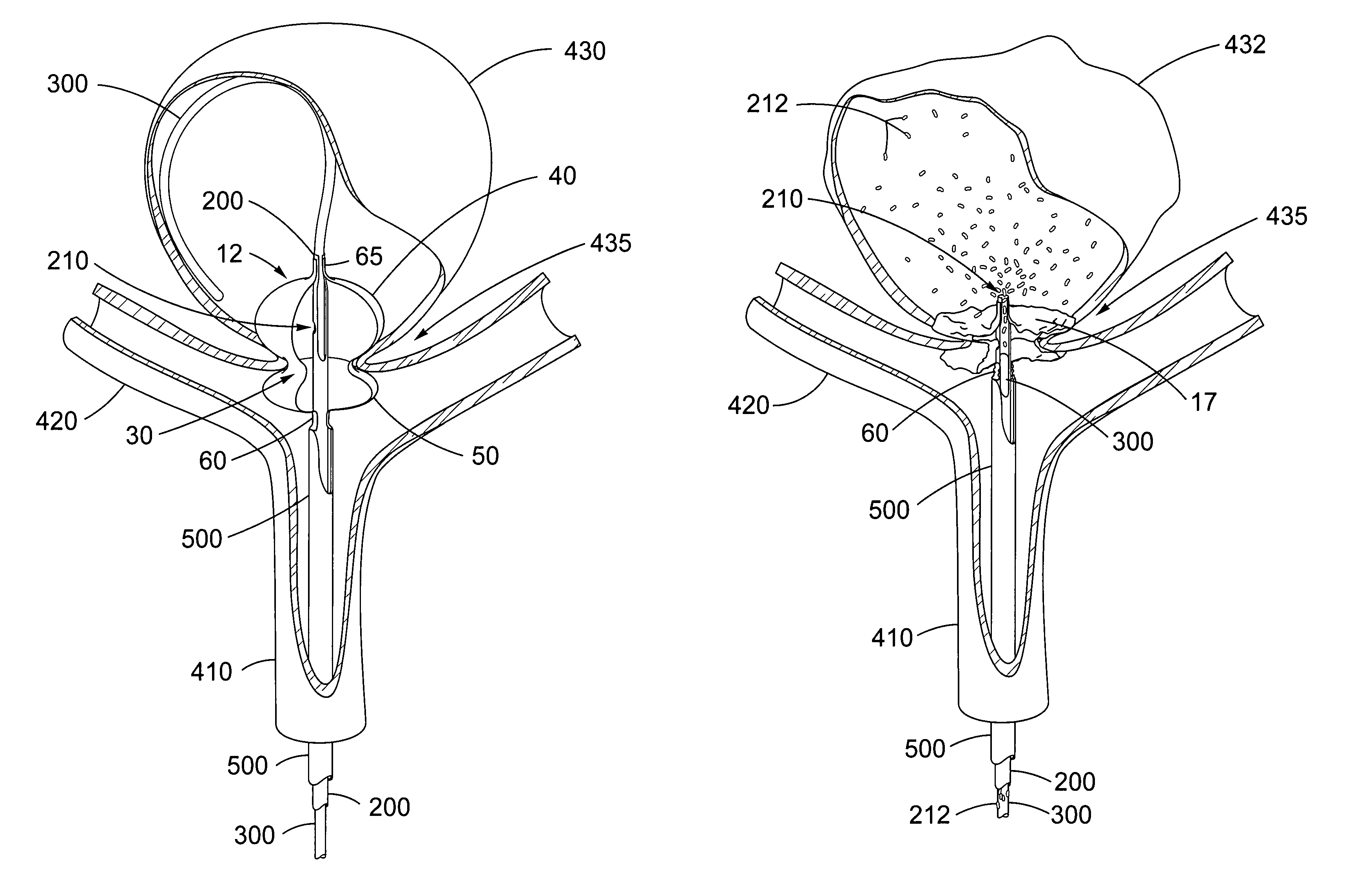
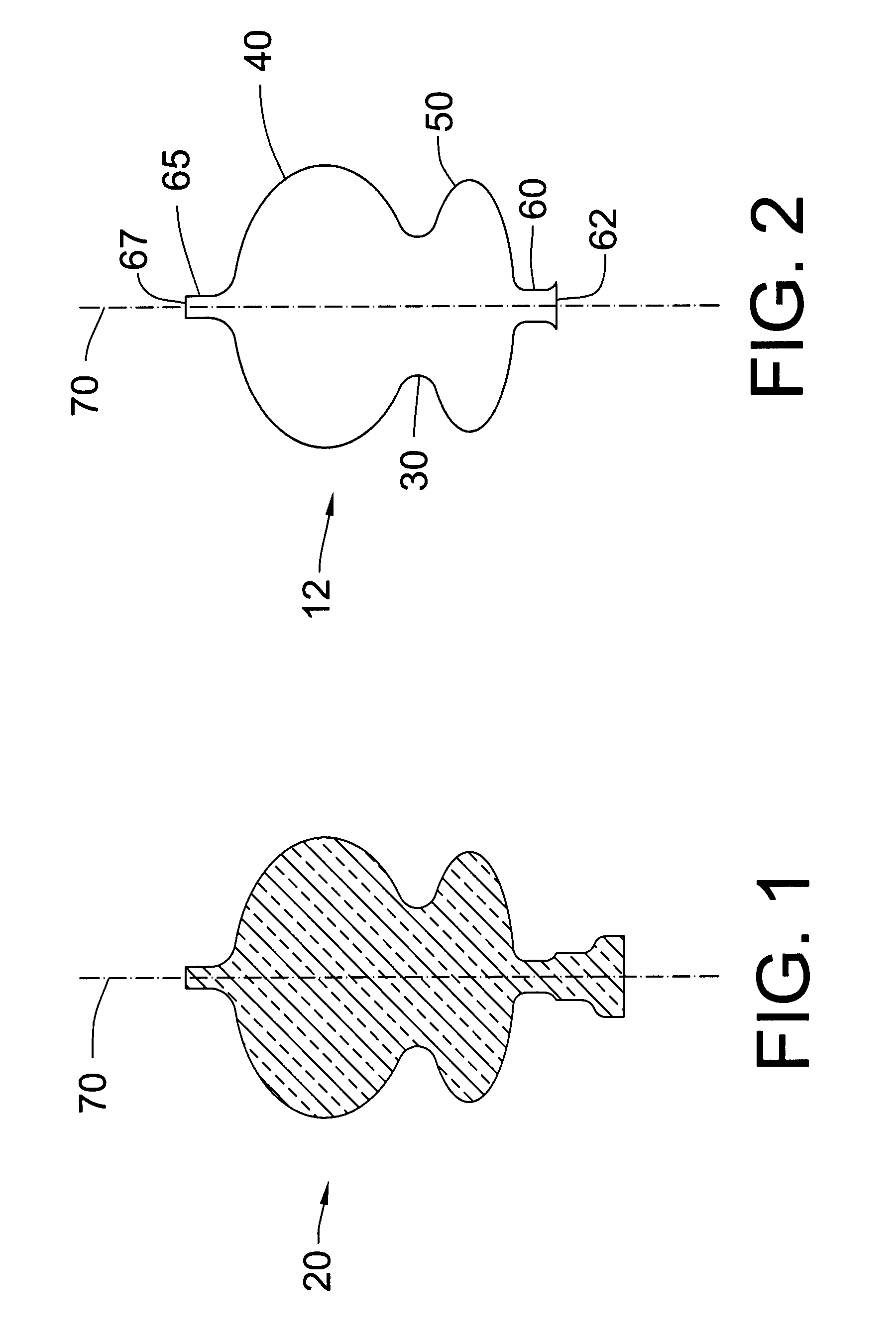
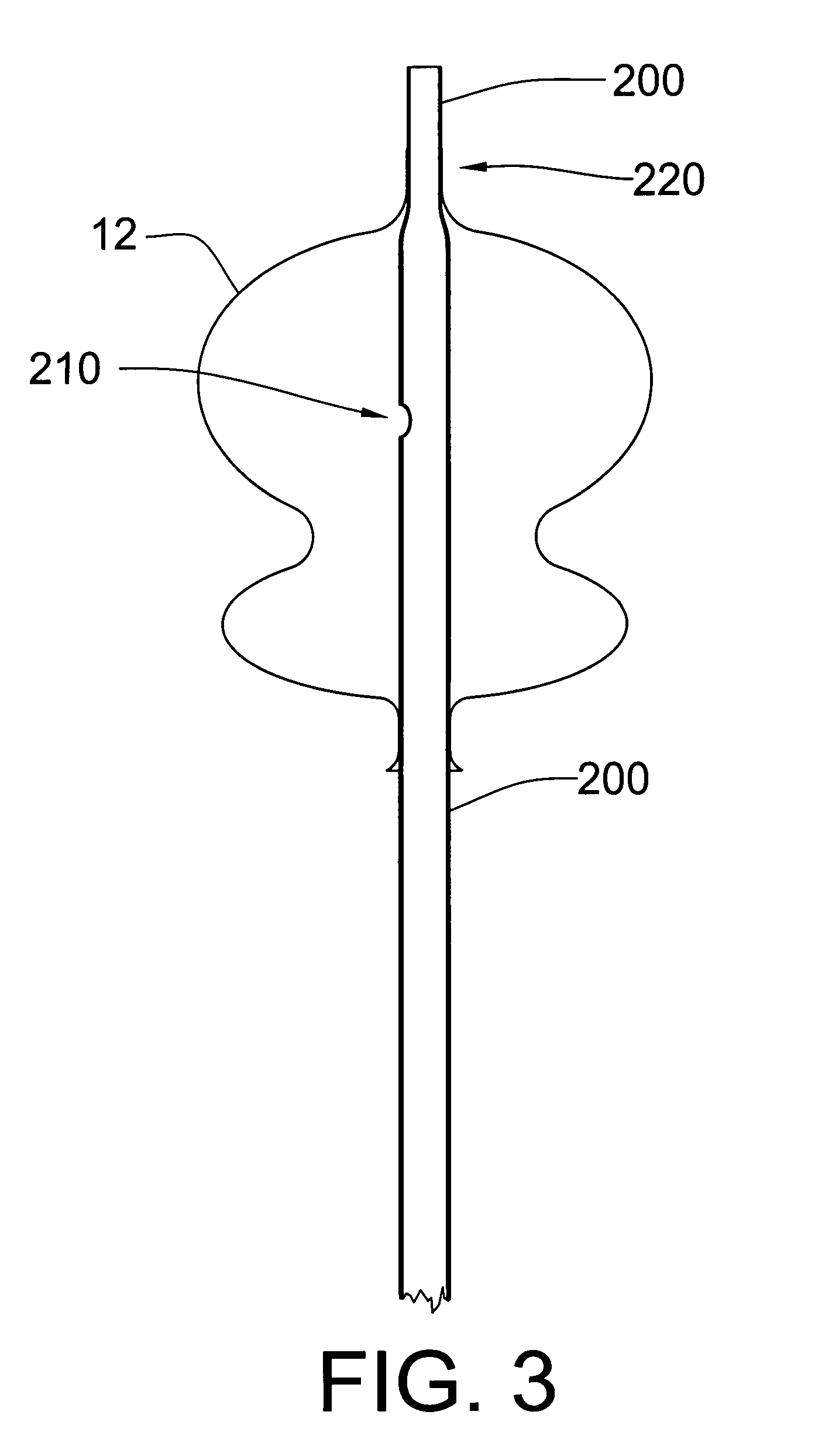
[0081]The current invention provides novel, non-obvious, and greatly useful improvements to applicants' earlier disclosed U.S. patent application Ser. No. 11 / 747,899 EXCLUSION DEVICE AND SYSTEM FOR DELIVERY. The present invention is a version of the exclusion device, which contains a second port and new delivery and collapse system. The currently disclosed over-the-guidewire exclusion device has many additional inventive features, relative to U.S. patent application Ser. No. 11 / 747,899, which facilitate mechanical collapse, blood aspiration and or drug introduction, stability upon delivery and deployment, and disconnection from the delivery catheter. The disclosed device is inherently connected with the disclosed novel endovascular delivery and deployment methods. In the illustrative embodiments depicted in FIGS. 1-13, an over-the-wire exclusion device 12 is delivered to an aneurysm 430, positioned at the neck 435 of the aneurysm, pressure expanded, and mechanically collapsed 17, th...


PUM


Abstract

A modification to allow delivery of a two port medical flow restrictor over a guidewire, and a means to mechanically collapse the new device. A thin walled, foil-like shell, is compacted for delivery. The invention includes the device, delivery assemblies, and methods of placing, and using, the device. A device with an aneurysm lobe and an artery lobe self-aligns its waist at the neck of an aneurysm as the device shell is pressure expanded. Mechanical force collapses both the aneurysm lobe and the artery lobe, captivating the neck of the aneurysm and securing the device. The device works for aneurysms at bifurcations and aneurysms near side-branch arteries. The device, unlike endovascular coiling, excludes the weak neck of the aneurysm from circulation, while leaving the aneurysm relatively empty. Unlike stent-based exclusion, the device does not block perforator arteries. This exclusion device can also limit flow through body lumens or orifices.

Description

CROSS-REFERENCE TO RELATED APPLICATIONS[0001]This application claims the benefit of priority under 35 U.S.C. §119(e) to provisional application No. 60 / 858,578 filed Nov. 13, 2006, and to provisional application No. 60 / 860,252 filed Nov. 21, 2006, each of which are incorporated herein by this reference.TECHNICAL FIELD[0002]The present invention relates to the field of medical intraluminal delivery of an implantable device that reduces or stops fluid movement that would otherwise flow or circulate through a body lumen or orifice. The invention is well suited for the treatment of neurovascular aneurysms or any other condition that could benefit by completely, or partially, excluding flow through a body orifice or vessel.BACKGROUND OF THE INVENTION[0003]An aneurysm forms when a dilated portion of an artery is stretched thin from the pressure of the blood. The weakened part of the artery forms a bulge, or a ballooning area, that risks leak or rupture. When a neurovascular aneurysm ruptur...

Claims


Application Information

Patent Timeline
Patent Type & Authority Patents(United States)
IPC IPC(8): A61F2/06
CPCA61B17/12022A61B17/12113A61B17/12136A61B17/12186A61M29/02A61B2017/12054
Inventor HINES, RICHARD A.
Owner ELECTROFORMED STENTS
Learn More