Electromechanical linear-motion actuator and electromechanical brake system

a technology of linear motion and actuator, applied in the direction of gearing, transportation and packaging, hoisting equipment, etc., can solve the problem of long axial length of the above-mentioned conventional electromechanical linear-motion actuator, and achieve the effect of shortening the axial length

Inactive Publication Date: 2013-02-19
NTN CORP
View PDF11 Cites 12 Cited by
  • Summary
  • Abstract
  • Description
  • Claims
  • Application Information

AI Technical Summary

Benefits of technology

[0009]In order to achieve this object, the present invention provides an electromechanical linear-motion actuator comprising a rotary shaft driven by an electric motor and having a radially outer surface, a stationary outer race member provided around the rotary shaft and having a radially inner surface, a plurality of planetary rollers disposed between the radially outer surface of the rotary shaft and the radially inner surface of the outer race member so as to be rotated about their own axes while revolving about the axis of the rotary shaft when the rotary shaft rotates, wherein a helical rib is provided on the radially inner surface of the outer race member or the radially outer surface of the rotary shaft, and wherein a helical groove or circumferential grooves are formed in a radially outer surface of each of the planetary rollers in which the helical rib is engaged, a planetary carrier axially facing the planetary rollers, and thrust rolling bearings disposed between the planetary carrier and the respective planetary rollers for preventing the rotation of the respective planetary rollers from being transmitted to the planetary carrier, characterized in that each of the thrust rolling bearings comprises a raceway formed on an axial end surface of the corresponding planetary roller. With this arrangement, it is possible to eliminate the need for a bearing race of each thrust rolling bearing on the planetary roller, and thus to reduce the axial length of the electromechanical linear-motion actuator by the amount equal to the axial thickness of this bearing race.
[0019]An electromechanical brake system of which the brake pads are driven by this electromechanical linear-motion actuator and pressed against the brake disc is also short in axial length. Thus, by mounting such an electromechanical brake system on a vehicle, it is possible to increase the freedom of layout of component parts surrounding the electromechanical brake system.

Problems solved by technology

But actually, the above-mentioned conventional electromechanical linear-motion actuator has a rather long axial length.

Method used


Image

  • Electromechanical linear-motion actuator and electromechanical brake system
  • Electromechanical linear-motion actuator and electromechanical brake system
  • Electromechanical linear-motion actuator and electromechanical brake system

Examples


first embodiment

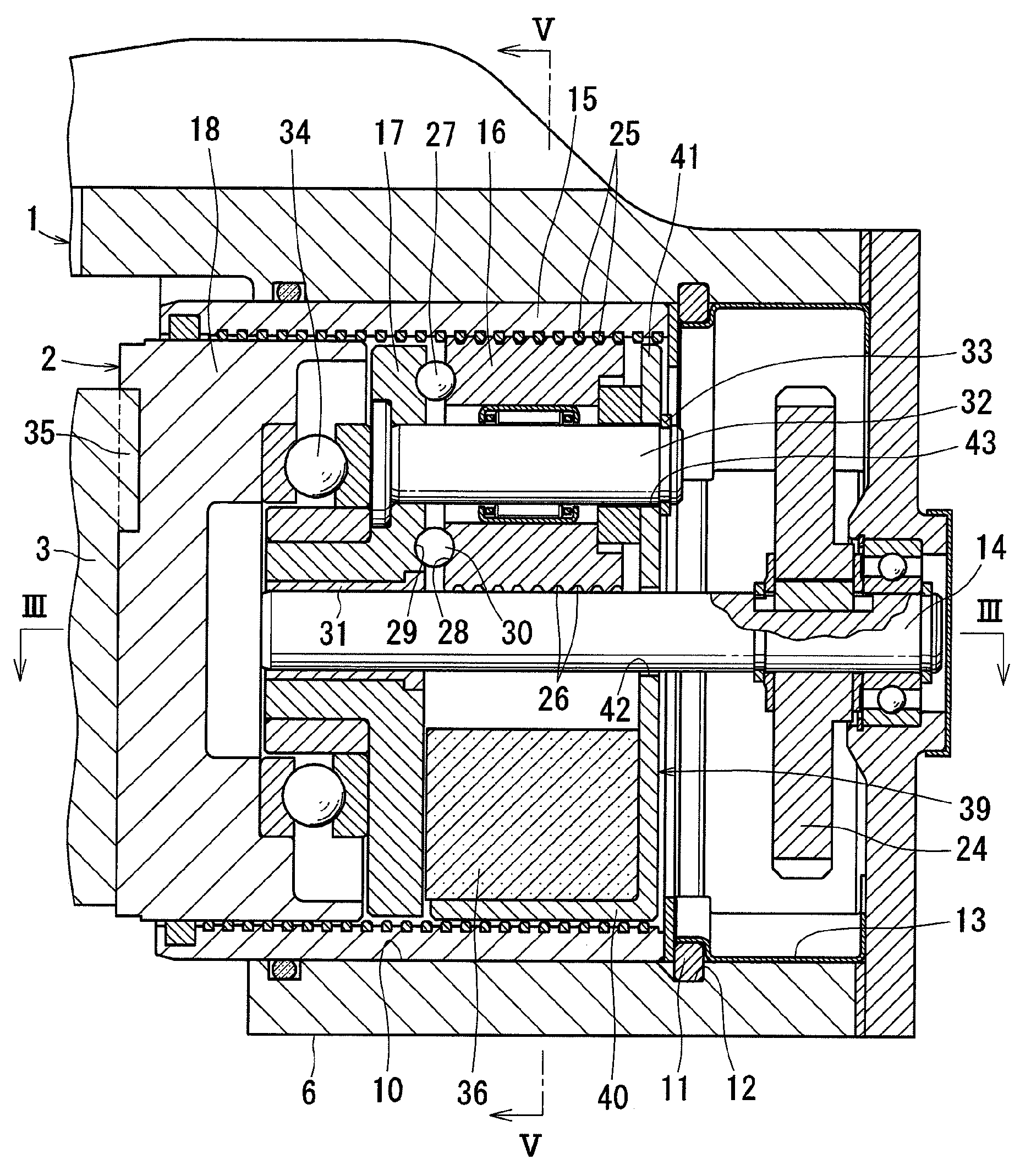
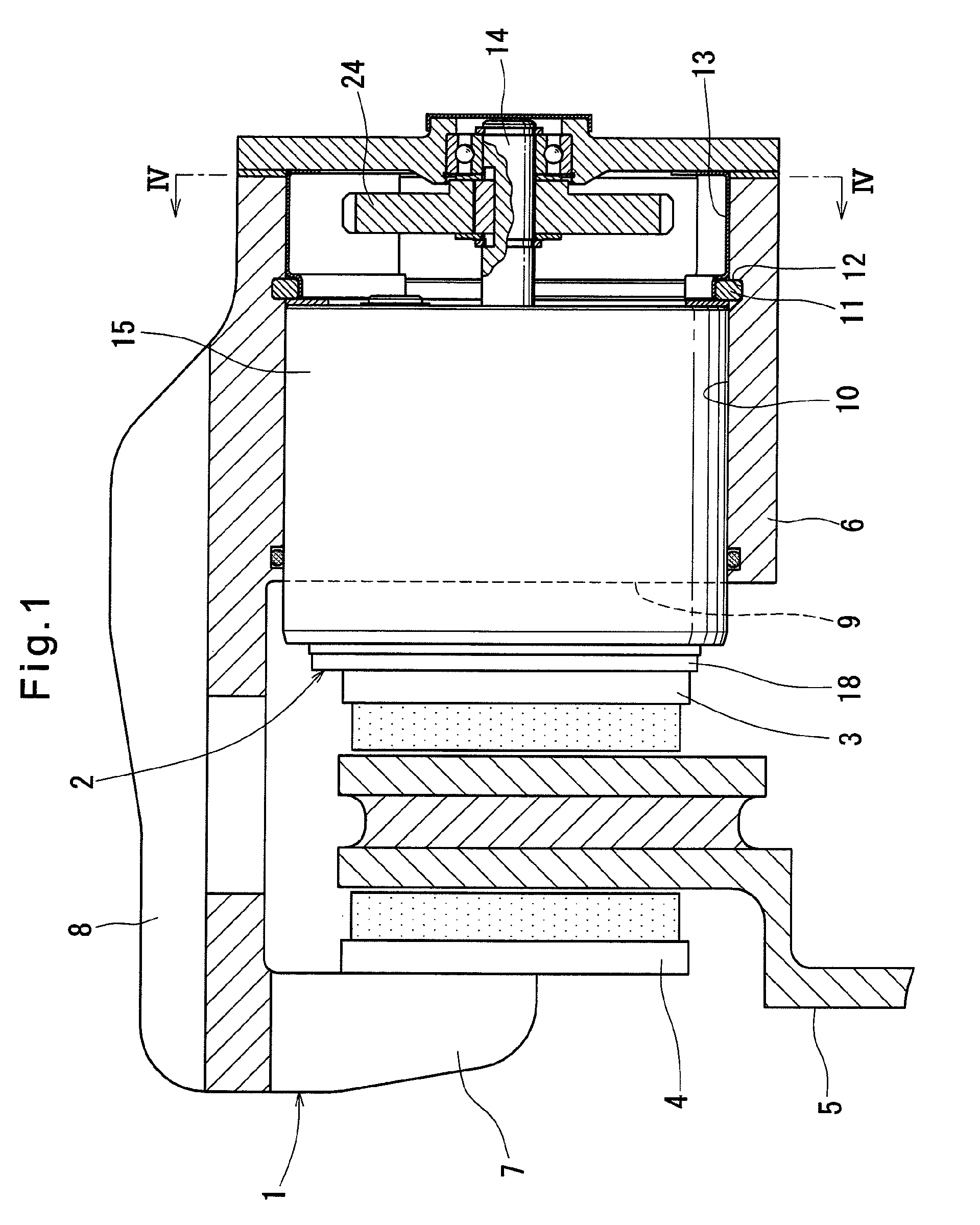
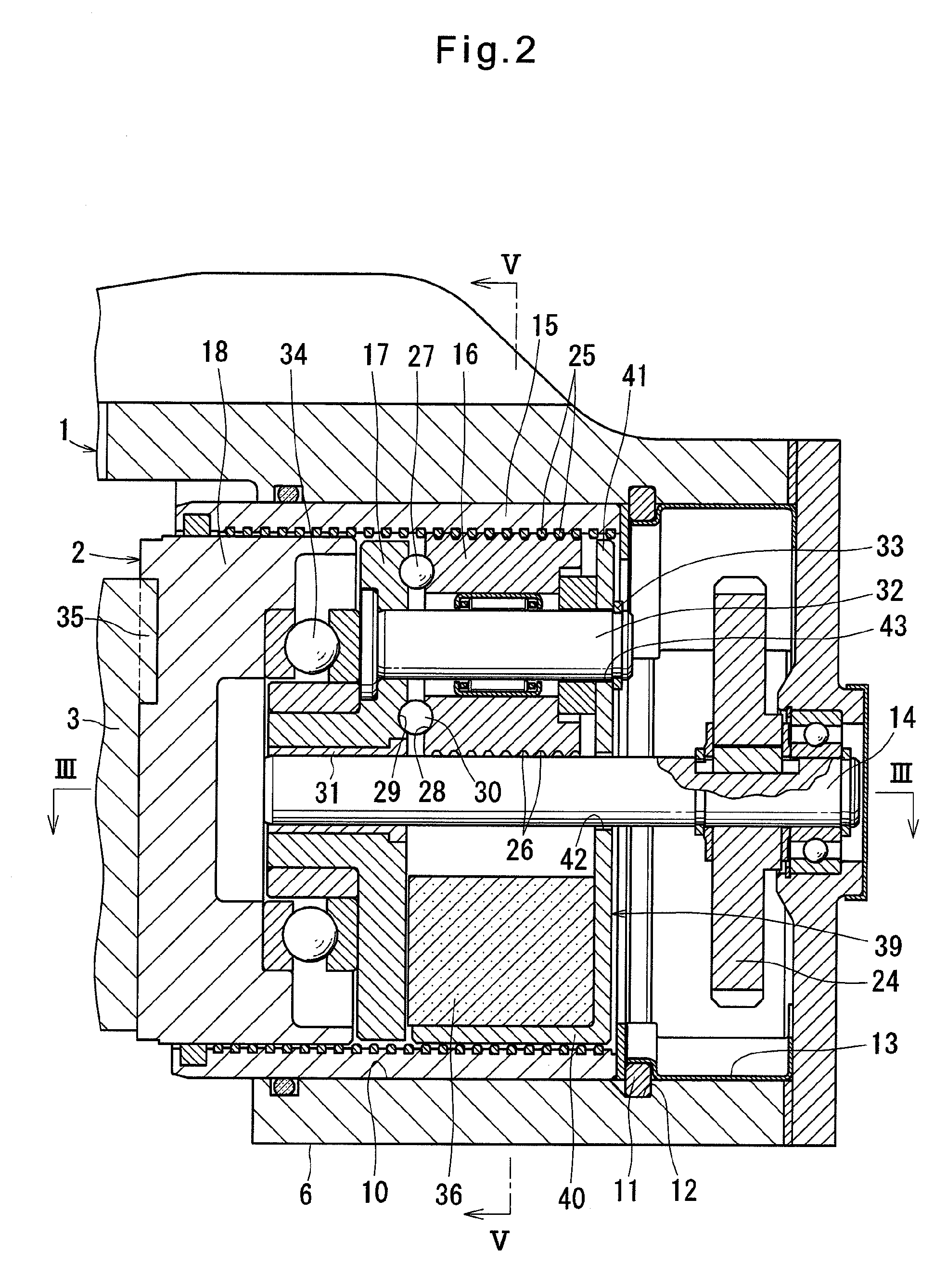
[0045]FIG. 1 shows an electromechanical brake system for use in vehicles. This electromechanical brake system comprises a caliper body 1, an electromechanical linear-motion actuator 2 according to the present invention, brake pads 3 and 4, and a brake disc 5.

[0046]The caliper body 1 comprises opposed portions 6 and 7 that oppose each other with the brake disc 5, which rotates together with a wheel, disposed therebetween, and a bridge portion 8 connecting the opposed portions 6 and 7 together. The caliper body 1 is supported on slide pins (not shown) so as to be axially slidable relative to the brake disc 5. An insertion hole 10 is formed in the surface 9 of the opposed portion 6 that opposes the brake disc 5. The electromechanical linear-motion actuator 2 is inserted in the insertion hole 10.

[0047]The brake pad 3 is disposed between the electromechanical linear-motion actuator 2 and the brake disc 5, and supported on pad pins (not shown) so as to be axially slidable relative to the ...

fourth embodiment

[0085]In the electromechanical linear-motion actuator 80 of the fourth embodiment, if circumferential grooves 84 are formed instead of the helical grooves 26, the circumferential ribs 85 may be formed on the radially outer surface of each lubricant applying member 81 that engage in the circumferential grooves 84 of the planetary rollers 61. With this arrangement, it is possible to directly apply lubricant to the inner surfaces of the circumferential grooves 84 formed in the radially outer surface of the planetary rollers 61.


PUM


Abstract

An electromechanical linear-motion actuator includes a rotary shaft, a stationary outer race member, and planetary rollers between the rotary shaft and the outer race member to rotate about their own axes and revolve around the rotary shaft axis. A helical rib is on the radially inner surface of the outer race member or the radially outer surface of the rotary shaft. A helical groove or circumferential grooves are formed in a radially outer surface of each of the planetary rollers in which the helical rib is engaged. A planetary carrier axially faces the planetary rollers, and thrust ball bearings are between the planetary carrier and the respective planetary rollers 16 for preventing rotation of the respective planetary rollers 16 from being transmitted to the planetary carrier 17. Each of the thrust ball bearings comprises a raceway formed on an axial end surface of the corresponding planetary roller.

Description

BACKGROUND OF THE INVENTION[0001]1. Technical Field[0002]This invention relates to an electromechanical linear-motion actuator for converting the rotation of a rotary shaft driven by an electric motor to axial movement of planetary rollers, and an electromechanical brake system in which this electromechanical linear-motion actuator is used.[0003]2. Background Art[0004]Conventional vehicle brake systems are mostly hydraulic systems, of which brake pads are driven by hydraulic cylinders and pressed against a brake disc. But with an introduction of anti-lock brake systems (ABS) and other brake control arrangements, electromechanical brake systems, which use no hydraulic circuit, are gathering attention these days. An electromechanical brake system includes an electromechanical linear-motion actuator mounted in a caliper body to convert the rotation of a rotary shaft driven by an electric motor to axial movement of planetary rollers. The axial movement of the planetary rollers is transm...

Claims


Application Information

Patent Timeline
Patent Type & Authority Patents(United States)
IPC IPC(8): F16D55/08
CPCF16D65/18H02K7/06F16H25/2252F16D2121/24F16D2125/40F16D2125/48F16D2125/50F16D2125/52Y10T74/18576F16H2025/2075F16H2025/2081F16H2025/209Y10T74/19795
Inventor YAMASAKI, TATSUYAEGUCHI, MASAAKI
Owner NTN CORP
Why Eureka
Try Eureka