Liquid ejecting head and liquid ejecting apparatus
a liquid ejecting head and liquid ejecting technology, which is applied in the direction of inking apparatus, device material selection, coatings, etc., can solve the problems of degradation of pzt thin films, and degradation of piezoelectric elements, so as to improve durability and reliability, the effect of reducing the degradation of device properties
- Summary
- Abstract
- Description
- Claims
- Application Information
AI Technical Summary
Benefits of technology
Problems solved by technology
Method used
Image


Examples
first embodiment
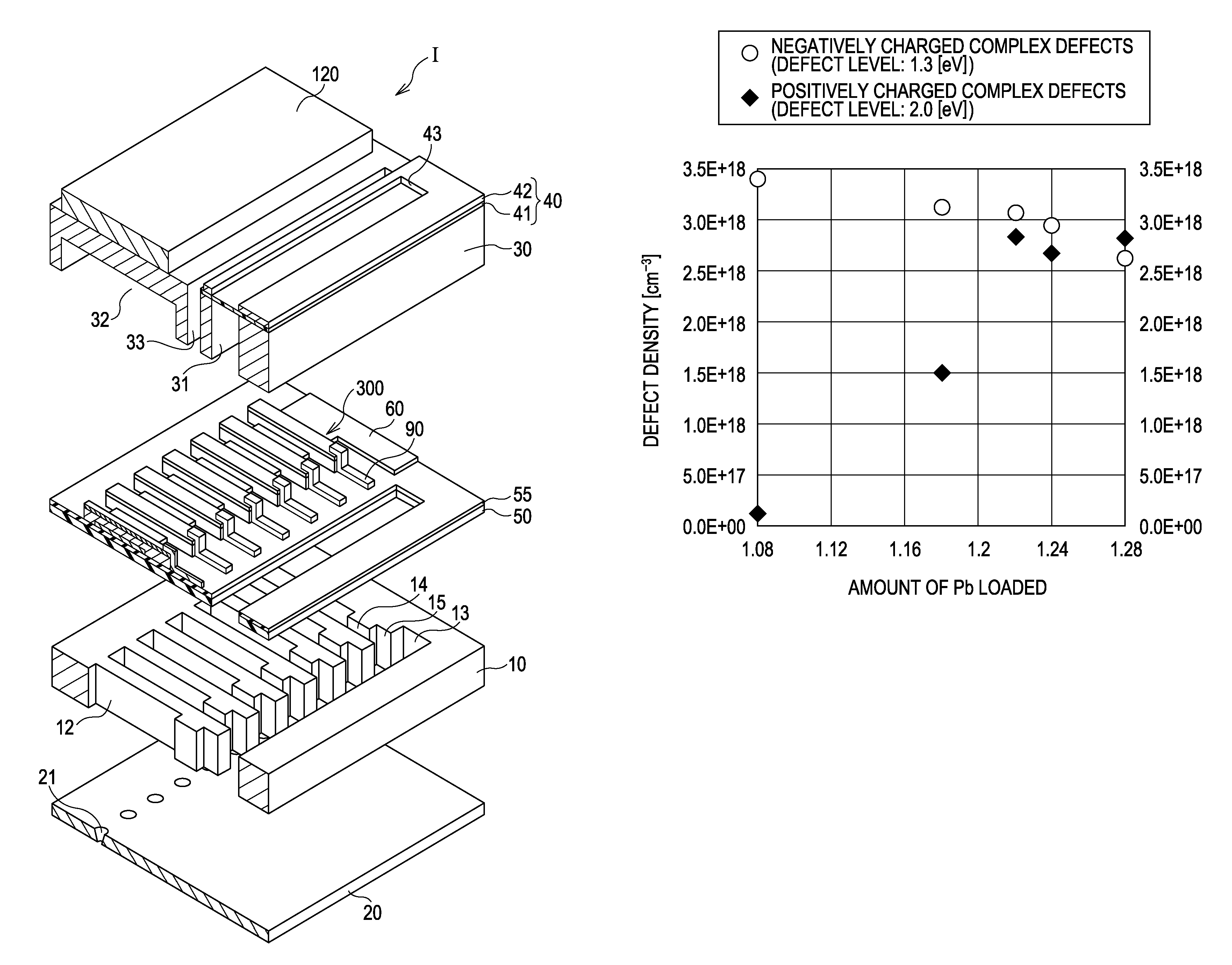
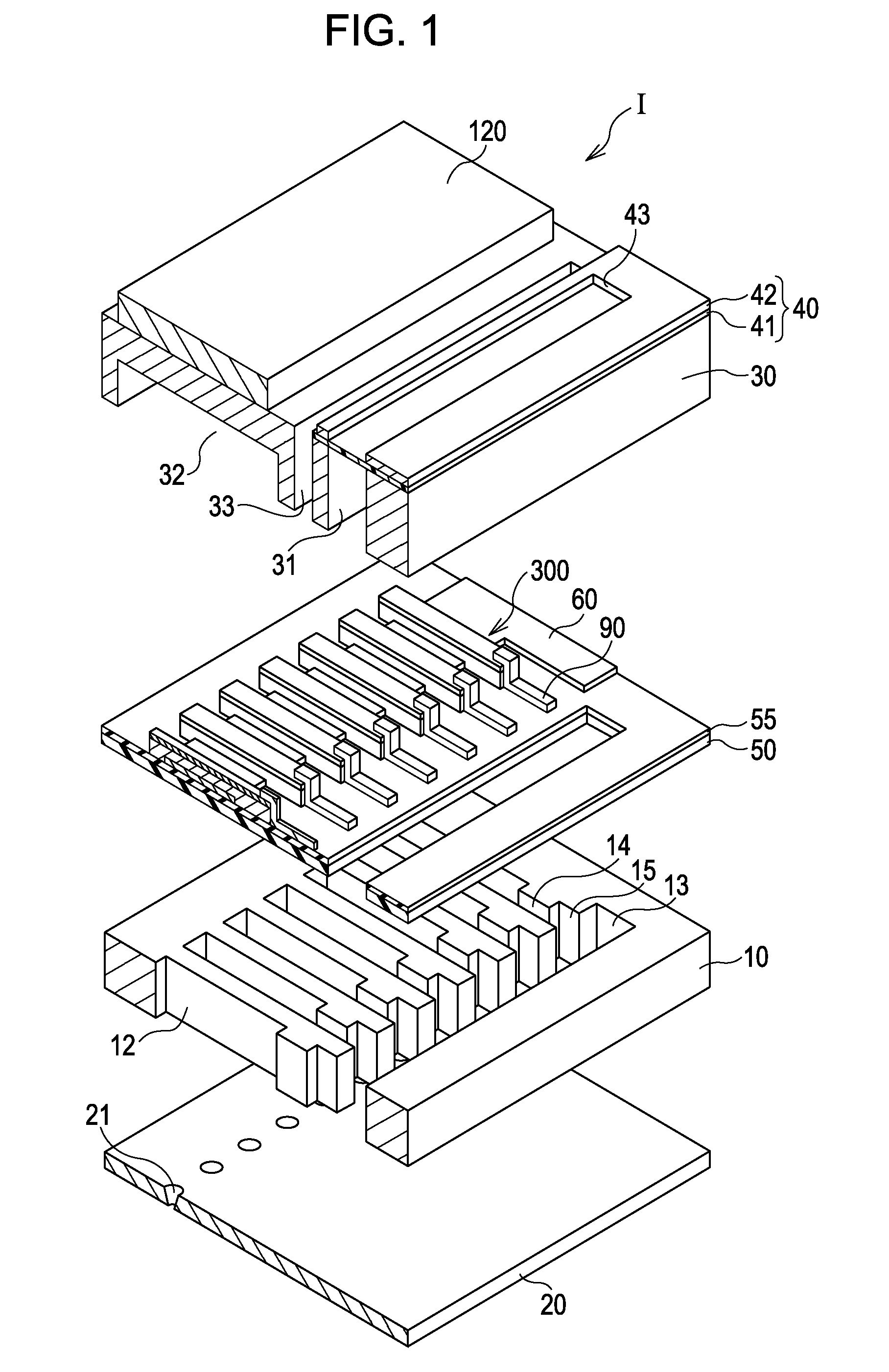
[0020]FIG. 1 is an exploded perspective view schematically showing a structure of an ink jet recording head, which is an example of a liquid ejecting head according to a first embodiment of the invention. FIGS. 2A and 2B are a plan view and a cross-sectional view taken along the line IIB-IIB in FIG. 2A, respectively, of the ink jet recording head shown in FIG. 1.
[0021]As shown in FIGS. 1, 2A, and 2B, a passage-forming substrate 10 according to this embodiment is made of a silicon single crystal substrate, and an elastic film 50 is disposed on one surface thereof.
[0022]A plurality of pressure-generating chambers 12 are placed in parallel in a width direction of the passage-forming substrate 10. A communicating portion 13 is provided in the passage-forming substrate 10 in a region located outside in the longitudinal direction of the pressure-generating chambers 12. The communicating portion 13 communicates with the pressure-generating chambers 12 through ink supply passages 14 and com...
examples
[0060]Piezoelectric layers were formed, in which by changing the amount of Pb loaded, the precursor crystallization temperature, the crystallization conditions, and the like, the concentration of complex defects were changed. Thus, Examples 1 to 4 and Comparative Example were prepared. The embodiment described above was considered as Example 3.
[0061]Table 1 shows the defect concentration of negatively charged Pb—O complex defects (minus defect concentration) and the defect concentration of positively charged Pb—O complex defects (plus defect concentration). These were calculated using the TSC technique as described above. The difference between the minus defect concentration and the plus defect concentration is shown as the net defect concentration in Table 1. A positive net defect concentration indicates that the minus defect concentration is higher than the plus defect concentration. That is, in Examples 1 to 4, the concentration of the negatively charged Pb—O complex defects is h...
PUM
 Abstract
Description
Claims
Application Information
 - R&D
- Intellectual Property
- Life Sciences
- Materials
- Tech Scout
- Unparalleled Data Quality
- Higher Quality Content
- 60% Fewer Hallucinations
Browse by: Latest US Patents, China's latest patents, Technical Efficacy Thesaurus, Application Domain, Technology Topic, Popular Technical Reports.
© 2025 PatSnap. All rights reserved.Legal|Privacy policy|Modern Slavery Act Transparency Statement|Sitemap|About US| Contact US: help@patsnap.com