Motor control apparatus and motor control method

a technology of motor control and control apparatus, which is applied in the direction of motor/generator/converter stopper, dynamo-electric converter control, and magnetic circuit shape/form/construction, etc., which can solve the problems of which is generated, and distortion in the waveform of the induced voltag

Active Publication Date: 2013-02-19
DENSO CORP
View PDF6 Cites 3 Cited by
  • Summary
  • Abstract
  • Description
  • Claims
  • Application Information

AI Technical Summary

Benefits of technology

[0011]The present invention addresses the above disadvantages. According to the present invention, there is provided a motor control apparatus for a polyphase electric motor that includes a rotor, which has a plurality of permanent magnets, and a stator core, which has a plurality of teeth and a plurality of windings. Each of the plurality of windings is provided for a corresponding one of a plurality of phases and is wound around each corresponding one of the plurality of teeth. The motor control apparatus includes a voltage applying means, a rotational speed sensing means, an obtaining means, a determining means and a correcting means. The voltage applying means is for sequentially applying a voltage to the plurality of windings on a phase-by-phase basis. The rotational speed sensing means is for sensing a rotational speed of the rotor, which is rotated by a rotating magnetic field that is generated by sequentially flowing an electric current in the plurality of windings on the phase-by-phase basis upon application of the voltage from the voltage applying means to the plurality of windings. The obtaining means is for obtaining an oscillation frequency of a periodic oscillation, which is generated in the polyphase electric motor at the rotational speed that is sensed with the rotational speed sensing means. The determining means is for determining whether the oscillation frequency, which is obtained with the obtaining means, is a predetermined resonance frequency. The correcting means is for correcting the voltage, which is applied from the voltage applying means to the plurality of windings, in a manner that reduces a resonance generated in the polyphase electric motor when the determining means determines that the oscillation frequency, which is obtained with the obtaining means, is the predetermined resonance frequency.

Problems solved by technology

However, in a real brushless motor, a distortion may occur in the waveform of the induced voltage, which is generated in each of the windings, due to magnetic saturation when an electric current flows under application of a load.
Also, a distortion may occur in the waveform when harmonic components of the induced voltages are overlapped in an interior permanent magnet (IPM) motor, in which permanent magnets are embedded in a rotor.
Furthermore, a distortion may occur in the waveform of the induced voltage due to a fluctuation in the load of the motor.
Therefore, in the brushless motor, when an electric current is supplied to the windings based on the induced voltage, a periodic oscillation may possibly be generated due to a torque ripple, a cogging and / or a load fluctuation in response to the distortion component of the induced voltage.

Method used


Image

  • Motor control apparatus and motor control method
  • Motor control apparatus and motor control method
  • Motor control apparatus and motor control method

Examples


Embodiment Construction

[0022]An embodiment of the present invention will be described with reference to the accompanying drawings.

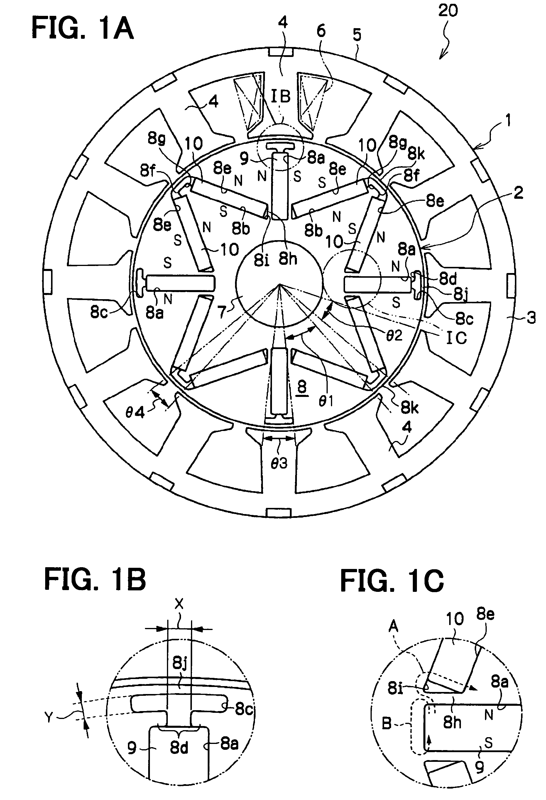
[0023]FIGS. 1A to 2 show a polyphase electric motor (hereinafter, simply referred to as a motor) 20 of the present embodiment.

[0024]As shown in FIG. 1A, the motor 20 includes a stator 1 and a rotor 2.

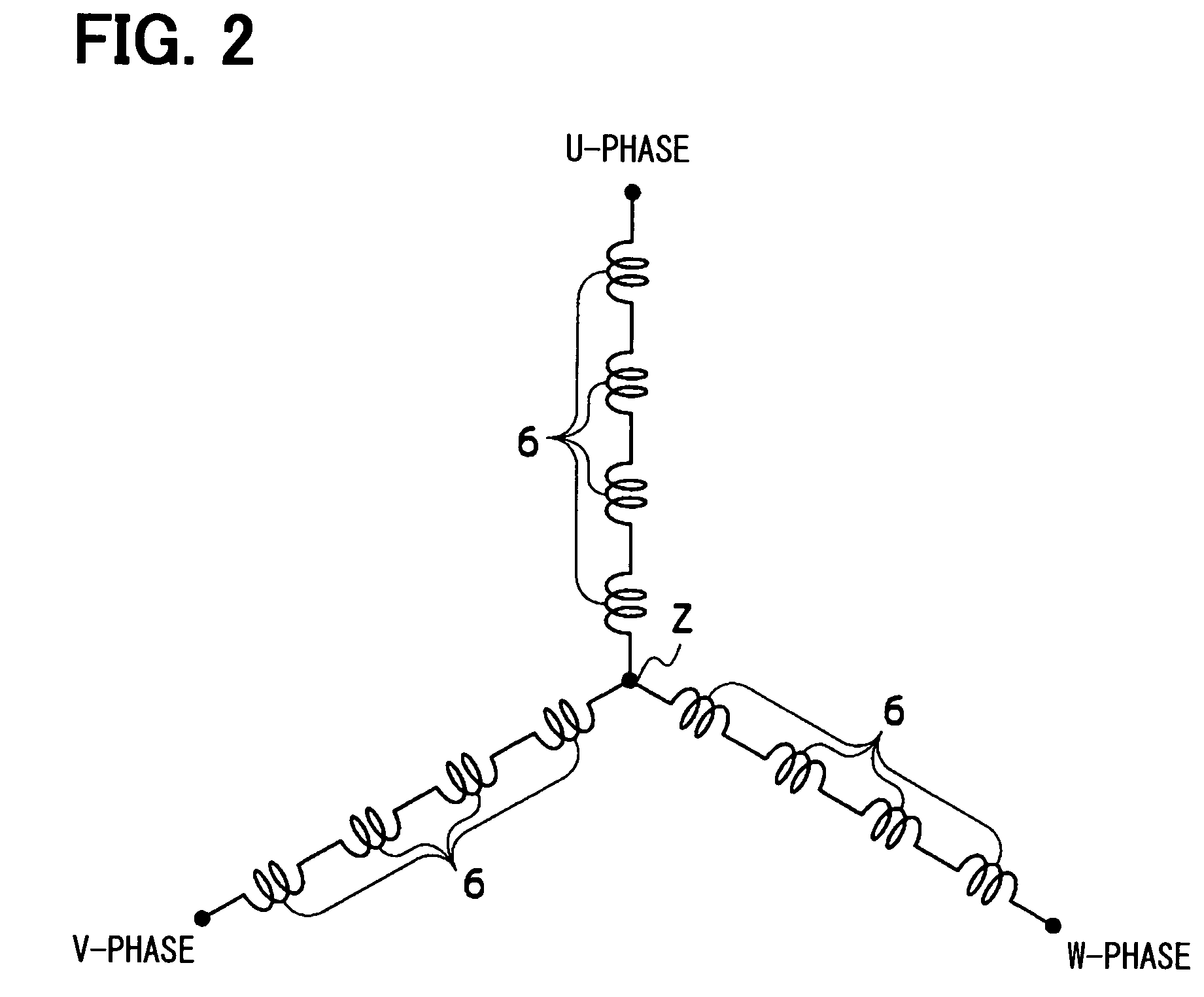
[0025]The stator 1 includes a stator core 5 and windings 6. The stator core 5 is configured as a generally cylindrical body and includes a cylindrical portion 3 and a plurality of teeth 4. The teeth 4 extend radially inwardly from an inner peripheral surface of the cylindrical portion 3, which defines an outer shape of the stator 1. The teeth 4 are arranged one after another at generally equal angular intervals in a circumferential direction. The windings 6 are wound around the teeth 4 in a concentrated winding pattern through an insulator (not shown). In FIG. 1A, only one of the windings 6, which is wound around one of the teeth 4, is indicated with a dot-dot-dash line. In the pre...


PUM


Abstract

In a polyphase electric motor, a voltage is sequentially applied to a plurality of windings on a phase-by-phase basis. Then, there is sensed a rotational speed of a rotor, which is rotated by a rotating magnetic field that is generated by sequentially flowing an electric current in the windings on the phase-by-phase basis upon the sequential application of the voltage to the windings. Then, an oscillation frequency of a periodic oscillation, which is generated in the motor at the sensed rotational speed of the rotor, is obtained. Thereafter, it is determined whether the obtained oscillation frequency is a predetermined resonance frequency. Next, the voltage to be applied to the windings is corrected in a manner that reduces a resonance generated in the motor when a result of the determination indicates that the obtained oscillation frequency is the predetermined resonance frequency.

Description

CROSS REFERENCE TO RELATED APPLICATION[0001]This application is based on and incorporates herein by reference Japanese Patent Application No. 2009-21525 filed on Feb. 2, 2009.BACKGROUND OF THE INVENTION[0002]1. Field of the Invention[0003]The present invention relates to a motor control apparatus and a motor control method.[0004]2. Description of Related Art[0005]A brushless polyphase electric motor (hereinafter, simply referred to as a brushless motor) is known as a motor having no brush and no commutator. Unlike a brush motor, in which brushes slidably engage a commutator, the brushless motor does not substantially have a frictional wearing and is thereby suitable for a long term use. Therefore, the brushless motor is widely used as a drive motor, which is frequently used and is disposed in an environment where a periodic maintenance work is not performed or is difficult to perform.[0006]In this brushless motor, the voltage is sequentially applied to windings of multiple phases on...

Claims


Application Information

Patent Timeline
Patent Type & Authority Patents(United States)
IPC IPC(8): H02K33/00H02K1/22H02K1/27H02K29/03H02K29/08H02P6/06H02P6/08H02P6/15H02P6/17H02P6/28H02P21/00H02P21/05H02P21/06H02P21/14H02P21/18H02P21/22H02P21/24H02P21/26H02P21/28H02P23/04H02P23/14H02P23/16H02P27/04H02P27/08
CPCH02P21/06
Inventor KANEKO, YOUICHI
Owner DENSO CORP
Why Eureka
Try Eureka