Field image tomography for magnetic resonance imaging

a field image and magnetic resonance imaging technology, applied in the field of magnetic resonance imaging methods and apparatuses, can solve the problems of slow mri in prior art, achieve fast mri, avoid the use of sedation, and reduce the length of time

Inactive Publication Date: 2013-02-19
SUBBARAO MURALIDHARA
View PDF9 Cites 29 Cited by
  • Summary
  • Abstract
  • Description
  • Claims
  • Application Information

AI Technical Summary

Problems solved by technology

A fundamental problem with MRI in prior art is that RF emitting nuclei are distributed in a 3D volume space (x,y,z) but only one fully parallel spatial encoding scheme is available, that is frequency encoding.
This makes MRI in prior art slow.

Method used


Image

  • Field image tomography for magnetic resonance imaging
  • Field image tomography for magnetic resonance imaging
  • Field image tomography for magnetic resonance imaging

Examples


Embodiment Construction

7.1 Apparatus of the Invention

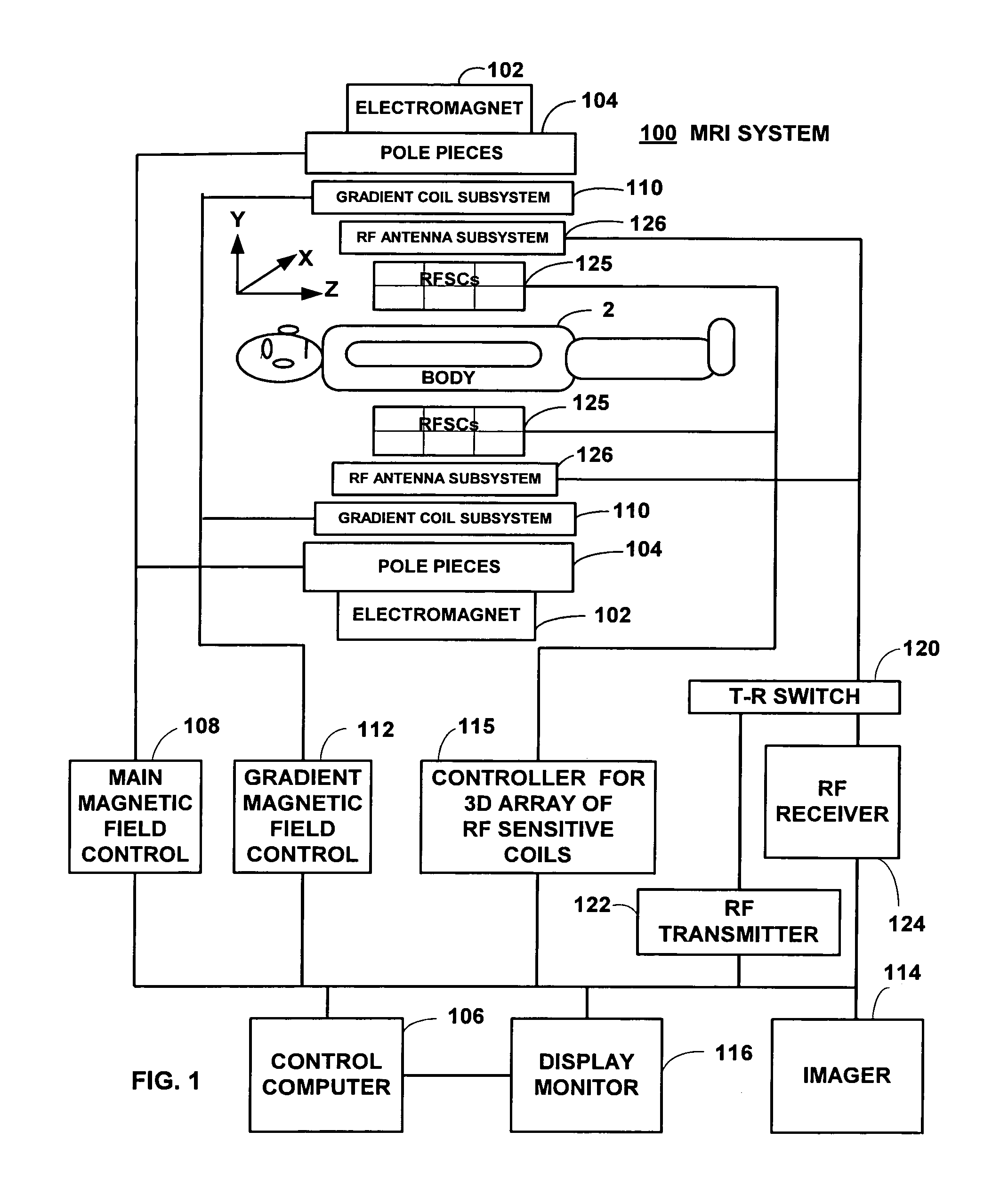
[0082]Referring now to the various figures of the drawing wherein like reference characters refer to like parts, there is shown in FIG. 1 a schematic view of an exemplary magnetic resonance imaging (MRI) system 100 adapted for use with the Field Image Tomography (FIT) according to the present invention. Although a MRI system having a main magnet comprising a certain-shaped magnet is illustrated, this shall not constitute a limitation. Reference is made to U.S. Pat. No. 4,968,937, the teachings of which are incorporated by reference for other details of the exemplary MRI system 100.

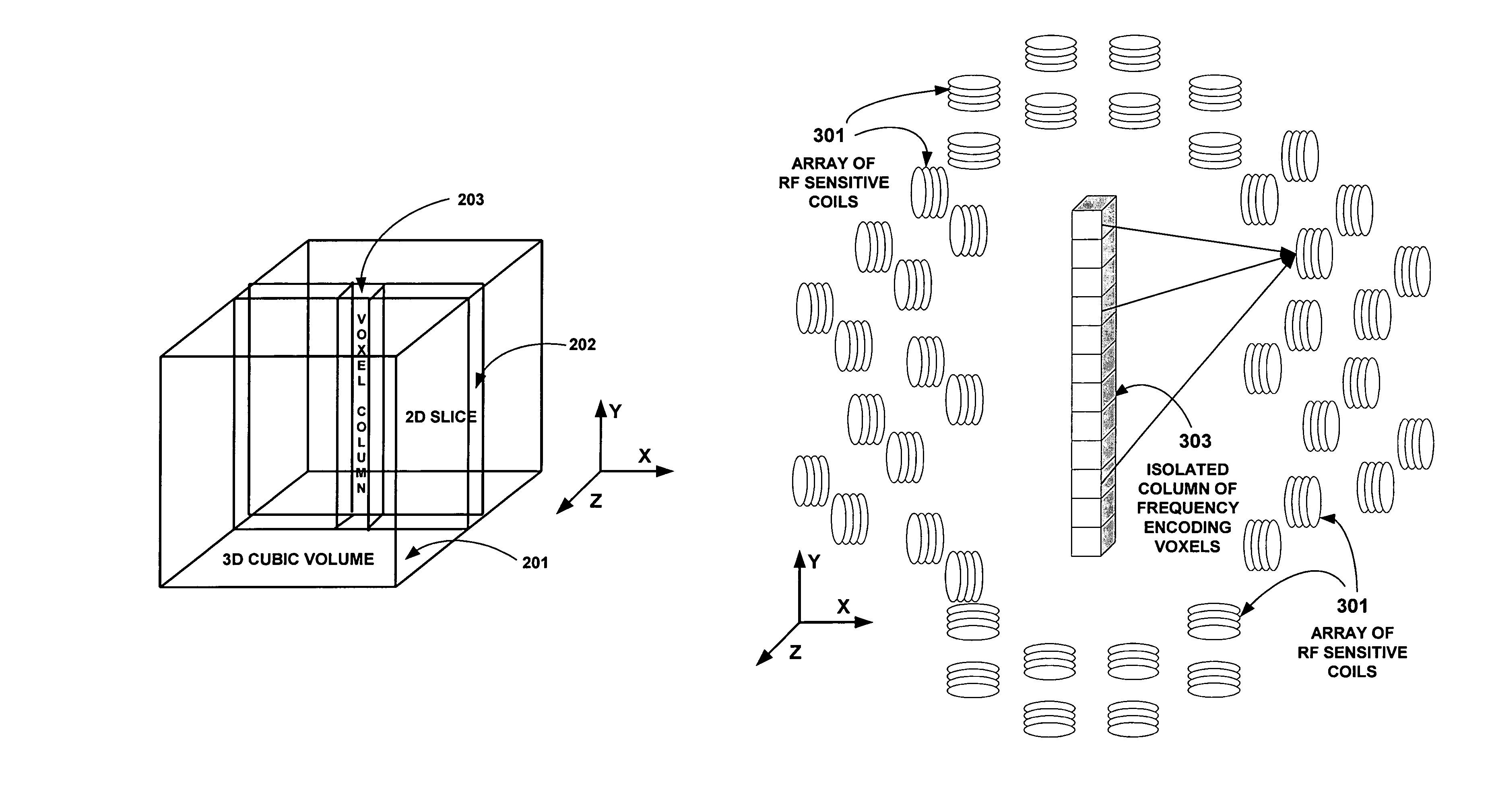
[0083]The MRI system 100 includes an electromagnet 102, a computer 106, a main magnetic field control 108, a gradient coil sub-system 110, a gradient field control 112, an imager 114, a display device 116, an RF antenna sub-system 126, a T / R switch 120, an RF transmitter 122 and a receiver 124. It also includes an array of RFSCs 125 in a non-degenerate configuration such as a ...


PUM


Abstract

Field Image Tomography (FIT) is a fundamental new theory for determining the three-dimensional (3D) spatial density distribution of field emitting sources. The field can be the intensity of any type of field including (i) Radio Frequency (RF) waves in Magnetic Resonance Imaging (MRI), (ii) Gamma radiation in SPECT / PET, and (iii) gravitational field of earth, moon, etc. FIT exploits the property that field intensity decreases with increasing radial distance from the field source and the field intensity distribution measured in an extended 3D volume space can be used to determine the 3D spatial density distribution of the emitting source elements. A method and apparatus are disclosed for MRI of target objects based on FIT. Spinning atomic nuclei of a target object in a magnetic field are excited by beaming a suitable Radio Frequency (RF) pulse. These excited nuclei emit RF radiation while returning to their normal state. The intensity or amplitude distribution of the RF emission field g is measured in a 3D volume space that may extend substantially along the radial direction around the emission source. g is related to the 3D tomography f through a system matrix H that depends on the MRI apparatus, and noise n through the vector equation g=Hf+n. This equation is solved to obtain the tomographic image f of the target object by a method that reduces the effect of noise.

Description

[0001]This patent application is a continuation of the following US Provisional Application for Patent filed by this inventor:[0002]M. Subbarao, “Field Image Tomography for Magnetic Resonance Imaging”, U.S. Provisional Patent Application No. 61 / 281,397, filed on Nov. 17, 2009.This patent application provides details of the description of the above invention.1. FIELD OF THE INVENTION[0003]The present invention relates to a method and apparatus for Magnetic Resonance Imaging (MRI) based on Field Image Tomography (FIT) first developed by this inventor recently and applied to SPECT (Single-Photon Emission Computed Tomography) and PET (Positron Emission Tomography) imaging. FIT is a fundamental new theory for determining the three-dimensional (3D) spatial density distribution of field emitting sources. FIT is based on the observation that the 3D spatial density distribution of a field source and the 3D field intensity distribution produced by the source in its vicinity in a 3D volume spa...

Claims


Application Information

Patent Timeline
Patent Type & Authority Patents(United States)
IPC IPC(8): G01V3/00
CPCG01R33/48G01R33/3415G01R33/481
Inventor SUBBARAO, MURALIDHARA
Owner SUBBARAO MURALIDHARA
Why Eureka
Try Eureka