Sensor aided direct gating for metal casting

a technology of metal casting and direct gating, which is applied in the direction of manufacturing tools, mold control devices, andfoundry moulding apparatus, etc., can solve the problems of not always ideal castings, casting defects frequently arise in complex castings, and riser metal not contributing to metal yield

Active Publication Date: 2013-03-05
GENERAL ELECTRIC CO
View PDF8 Cites 17 Cited by
  • Summary
  • Abstract
  • Description
  • Claims
  • Application Information

AI Technical Summary

Benefits of technology

[0006]A mold system is set forth wherein the mold system includes a first sprue and a second sprue and a pouring basin arrangement for selectively feeding molten metal to the first sprue and the second sprue. The mold includes a mold cavity. A first gating system having a feed or opening, into the mold cavity provides fluid communication between the first sprue and a first portion of the mold cavity. A second gating system having a feed, or opening, into the mold cavity provides fluid communication between the second sprue and a second portion of the mold cavity. The feed of the second gating system supplies the mold cavity with fluid above the feed for the first gating system. The mold system may include a first stopper that is associated with the first sprue to regulate fluid flow through the first sprue. The fluid is molten metal. The mold system may further include a second stopper associated with the second sprue regulates molten metal flow through the second sprue. A sensor in the mold determines the level of the molten metal within the mold cavity. Whether the stoppers are required depends on the pouring basin arrangement. When sepa

Problems solved by technology

Casting defects frequently arise in complex castings as a result of shrinkage in the last regions of the casting to solidify.
Castings are not always ideal, and the heaviest section, if

Method used


Image

  • Sensor aided direct gating for metal casting
  • Sensor aided direct gating for metal casting
  • Sensor aided direct gating for metal casting

Examples


first embodiment

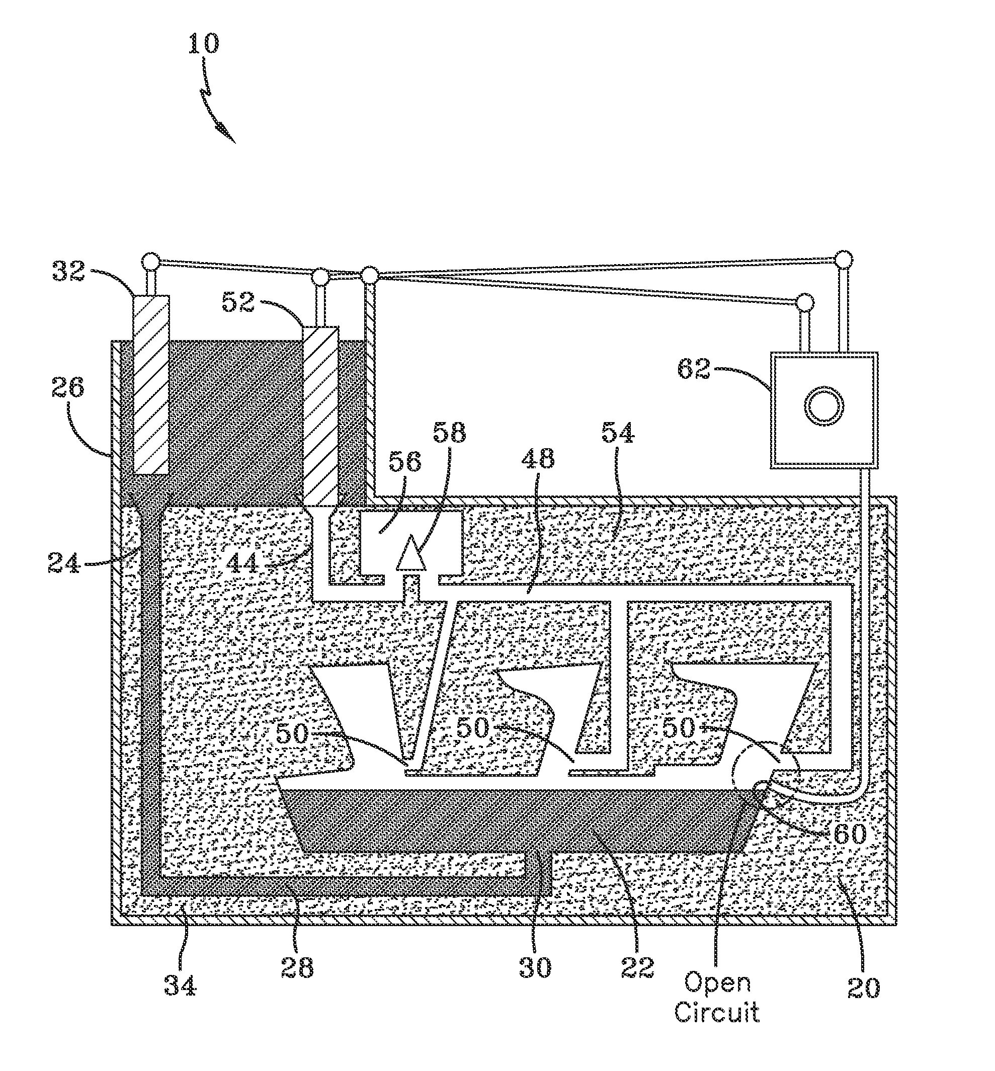
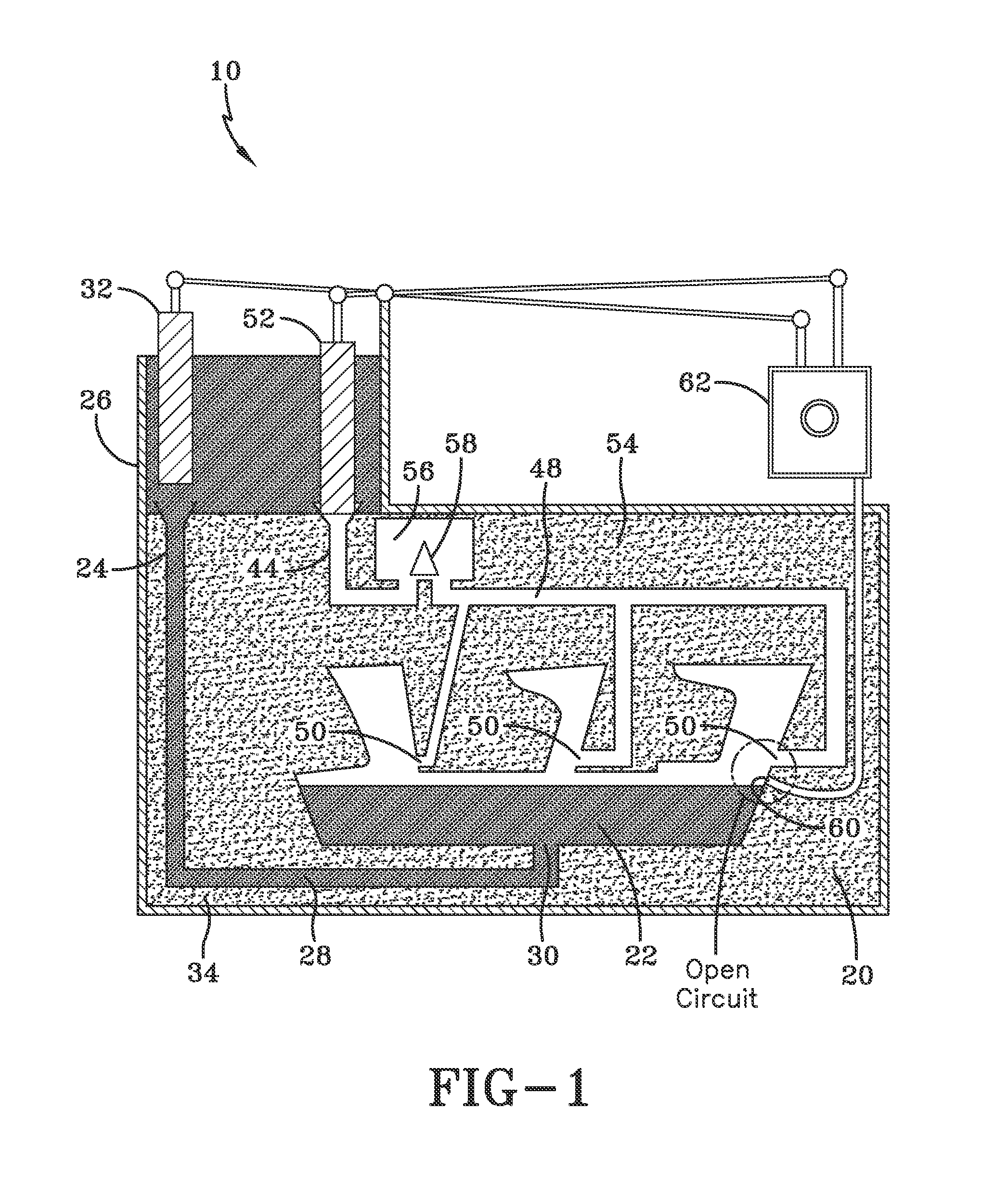
[0020]Referring now to FIG. 1, mold system 10 is set forth. In this embodiment, the article that is cast is a complex item such as a turbine or compressor casing, wherein the thinner sections of the casing are positioned in the top portion of the mold and the thicker sections of the casing are positioned in the bottom portion of the mold. However, the mold system of the present invention is suitable for other structural applications, including but not limited to a compressor discharge case. The mold system of the present invention is usable not only for many turbine alloys, such as cast steel, cast iron, cast superalloy, and titanium alloys, but also for any alloy that is usable in cast form. Mold system 10 includes a mold 20 having a mold cavity 22. A first sprue 24 extends from a pouring basin or pouring cup 26. First sprue 24 provides fluid communication between pouring cup 26 and first gating system 28. First gating system provides fluid communication between first sprue 24 and ...

second embodiment

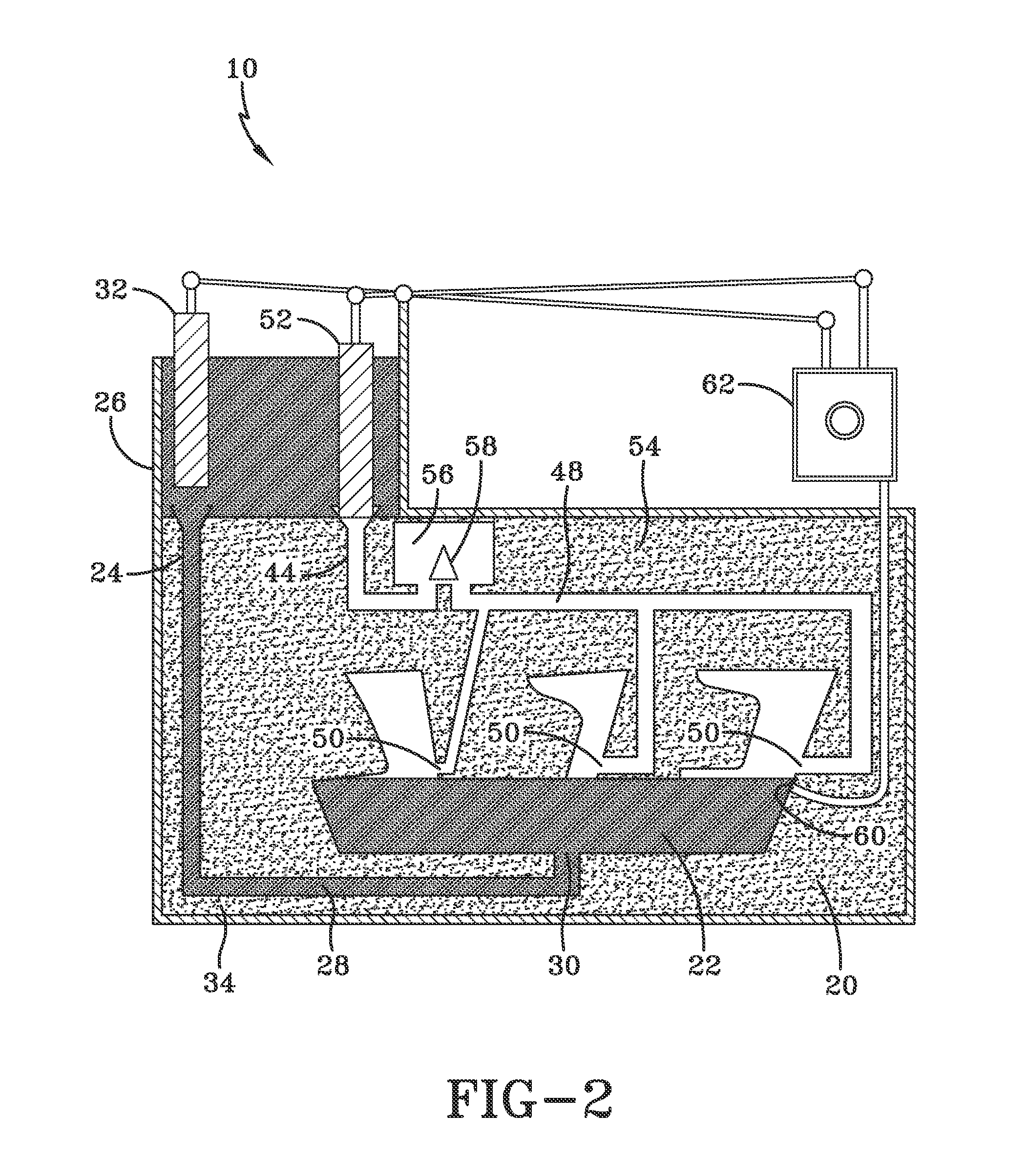
[0032]In the second embodiment, mold system 110 includes a mold 20 having a mold cavity 122. A first sprue 24 extends from a pouring basin or pouring cup 26. First sprue 24 provides fluid communication between pouring cup 26 and first gating system 28. First gating system provides fluid communication between first sprue 24 and mold cavity 122 through first feed or opening 30. A first stopper 32 movable in relation to first sprue 24 controls the flow of fluid, which typically is molten metal in a casting operation, from pouring cup 26 through first circuit 34, which includes first stopper 32, first sprue 24, first gating system 28 and first feed 30 into mold cavity 122.

[0033]Mold system 110 includes a second circuit 154 which comprises a second stopper 52, a second sprue 44, a second gating system 148 and a second feed 150. In second circuit 154, second stopper 52 regulates the flow of molten metal from pouring basin 26 into second sprue 44, which is in fluid communication with mold ...


PUM

PropertyMeasurementUnit
Temperatureaaaaaaaaaa
Flow rateaaaaaaaaaa
Heightaaaaaaaaaa

Abstract

A mold system and method for producing a casting. The mold system utilizes multiple channels, each channel comprising a sprue and gating system, to feed the mold cavity at different heights. When a lower portion of the mold is filled, a controller is signaled to initiate filling of the mold through a second channel positioned above the lower portion. This mold system desirably provides the hottest molten metal to the last portion of the casting to freeze with or without the use of risers, eliminating casting defects. The system also enables the controlled pouring of dissimilar metal castings.

Description

FIELD OF THE INVENTION[0001]The present invention is directed to molds for metal casting, and specifically for efficiently delivering molten metal to regions of a casting where shrinkage is expected.BACKGROUND OF THE INVENTION[0002]Casting defects frequently arise in complex castings as a result of shrinkage in the last regions of the casting to solidify. Ideally, in casting design, sections most distant from available liquid metal will solidify first, and liquid metal will be available to feed the solidifying metal to prevent shrinkage. This solidification process, in an ideal casting, continues until the heaviest and last-to-freeze section is reached.[0003]Castings are not always ideal, and the heaviest section, if there is one, may not always be the last section to freeze. To deal with this, mold designers include risers, which provide reservoirs of molten metal to feed hot molten metal to the casting as it solidifies. The primary function of the riser is to feed molten metal to ...

Claims


Application Information

Patent Timeline
IPC IPC(8): B22D35/04B22D37/00
CPCB22D35/04B22D37/00
Inventor PARK, JUNYOUNGPAROLINI, JASON ROBERTSCHAEFFER, JON CONRAD
Owner GENERAL ELECTRIC CO
Why Eureka
Try Eureka