Liquid separation device, flow channel material and process for producing the same

a separation device and flow channel technology, applied in separation processes, membranes, knitting, etc., can solve the problems of deteriorating treatment efficiency, reducing the number of units capable of being inserted into the module, and reducing the width of the groove, so as to prevent the function of the separation membrane from deteriorating, the effect of lowering the resistance of the flow channel

Inactive Publication Date: 2013-03-05
TORAY IND INC
View PDF15 Cites 44 Cited by
  • Summary
  • Abstract
  • Description
  • Claims
  • Application Information

AI Technical Summary

Benefits of technology

[0008]The present invention provides a liquid separation device preventing a separation membrane from falling in, and having a small flow channel resistance by improving drawbacks of the conventional techniques, narrowing the width of a groove and increasing the number of grooves per unit width of a flow channel material without increasing constituent materials, production processes and the whole thickness.
[0011]According to an embodiment of the present invention, the groove width of a linear groove relative to the pitch of a linear groove can be increased, so the number of grooves per unit width of a flow channel material can be increased without narrowing the groove width. Hence, it becomes possible to achieve a shape ensuring a cross-sectional area of a groove per unit width of a permeated liquid flow channel material and lowering the flow channel resistance as well as narrowing the groove width of a flow channel material to prevent a separation membrane from falling in the groove of a permeated liquid flow channel material. As a result, it becomes possible to prevent a reverse osmosis membrane from falling in without increasing constituent materials, production processes and the whole thickness, and it becomes possible to ensure a flow channel of the permeated liquid and prevent deterioration of the function of the separation membrane.

Problems solved by technology

However, the former method of laminating a flat fabric poses a problem that constituent materials and production processes increase, deteriorating a production efficiency.
On the other hand, the latter method that flow channels are provided on both surfaces of a flow channel material by using a double tricot also poses a problem that the number of units capable of being inserted into a module decreases because the total thickness becomes large, and deteriorating a treatment efficiency.
Since tricot cannot narrows the width of a linear crest, it is not possible to increase the number of channels per unit width of a flow channel material.
Therefore, the channel width must be widened to reduce the flow channel resistance of permeated liquid; by doing so, there is a problem that a reverse osmosis membrane undergoes a creep deformation with time and falls in.

Method used


Image

  • Liquid separation device, flow channel material and process for producing the same
  • Liquid separation device, flow channel material and process for producing the same
  • Liquid separation device, flow channel material and process for producing the same

Examples


example 1

[0057]Measurement techniques and simulation techniques were conducted.

>

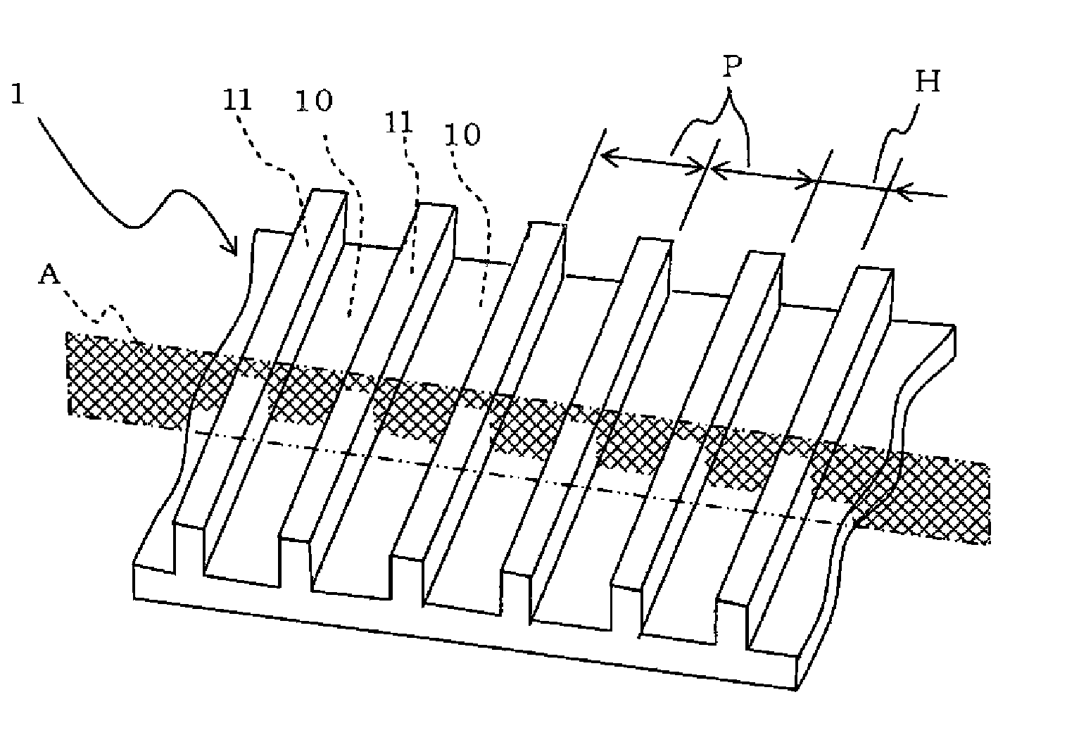
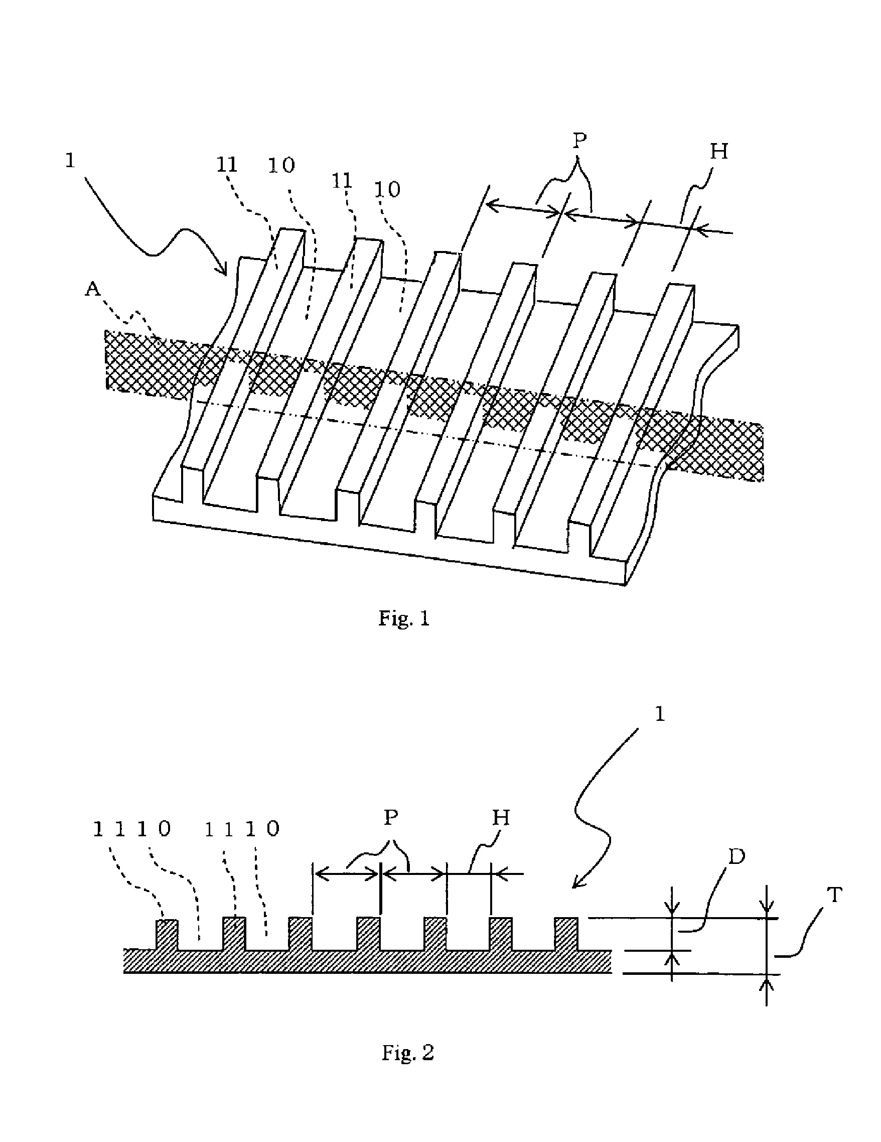
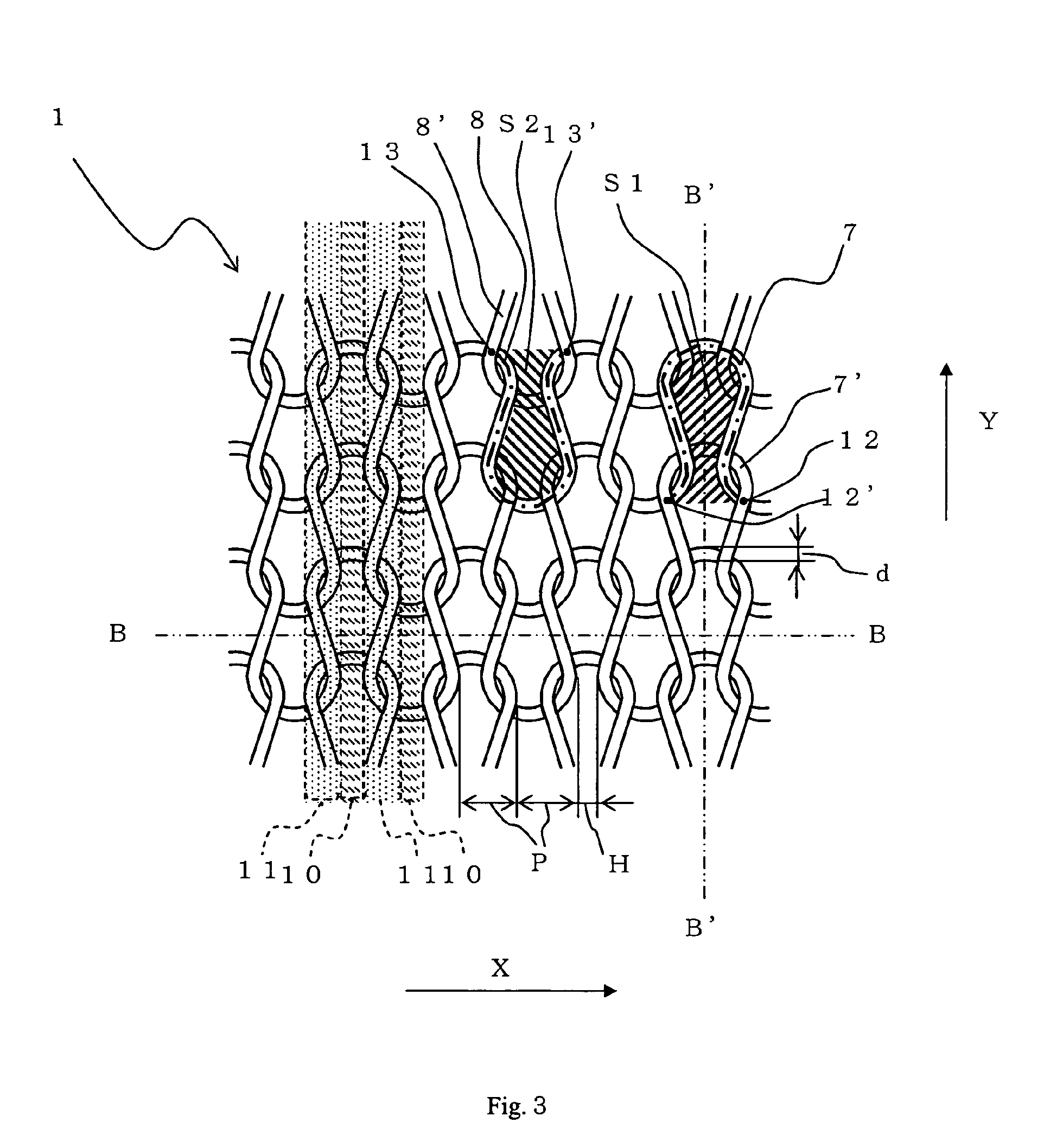
[0058]A multi-filament yarn (48 filaments, 110 dtex) that a polyethylene terephthalate filament (melting point: 255° C.) was mixed with a polyethylene terephthalate-type lower melting point filament (melting point: 235° C.) was used as a knitting yarn; a weft knit structure of a plain knitting (gauge (the number of needles per unit length in a knitting machine) 32) was knitted, which was subjected to thermal setting at 245° C., then to calendering, thereby to produce a permeated liquid flow channel material that the groove width was 130 μm, a ratio of the groove width to the pitch of a linear groove was 0.52, the depth of a linear groove was 110 μm, the thickness was 220 μm and a ratio [S1 / (S1+S2)] of needle loop area (S1) to the sum of needle loop area (S1) and sinker loop area (S2) was 0.48.

[0059]When a reverse osmosis module incorporated with this permeated liquid flow channel material was used, the volume of ...

example 2

[0061]Evaluations were conducted by the same simulation technique as in Example 1 except for using a permeated liquid flow channel material that the groove width was 80 μm, a ratio of the groove width to the pitch of a linear groove was 0.50, the depth of a linear groove was 80 μm and the thickness was 170 μm. As a result, the liquidity of permeated liquid was good, and there was no damage in both membrane and permeated liquid flow channel material.

example 3

[0062]Evaluations were conducted by the same simulation technique as in Example 1 except for using a permeated liquid flow channel material that the groove width was 192 μm, a ratio of the groove width to the pitch of a linear groove was 0.90, the depth of a linear groove was 21 μm and the thickness was 50 μm. As a result, the liquidity of permeated liquid was good, and there was no damage in both membrane and permeated liquid flow channel material.


PUM

PropertyMeasurementUnit
widthaaaaaaaaaa
outer diameteraaaaaaaaaa
depthaaaaaaaaaa

Abstract

A liquid separation device is provided, and is capable of suppressing the lowering of filtration function due to an increase in flow channel resistance of permeated liquid which results in a separation membrane falling in a groove of a permeated liquid flow channel material along with accompanied breakage of the separation membrane surface. A permeated liquid flow channel material is disposed on the back side of a separation membrane composed of a sheet-like material having a linear groove and a linear crest alternately arrayed on one surface or both surfaces, wherein a groove width of the linear groove in the sheet-like material is 10 to 200 μm, and a ratio of the groove width of the linear groove to the pitch of the linear groove is 0.45 or more.

Description

[0001]This is a U.S. National Phase application of application number PCT / JP2007 / 055944, filed Mar. 23, 2007 (which is incorporated herein by reference in its entirety), which claims priority benefit of JP 2006-097161 (filed Mar. 31, 2006).TECHNICAL FIELD[0002]The present invention relates to a liquid separation device characterized by improvement of a flow channel material mainly disposed on the back side of a separation membrane.BACKGROUND OF THE INVENTION[0003]In one of water purifier systems, there is a water purifier system using a reverse osmosis membrane, a nanofiltration membrane or the like, and liquid separation devices such as spiral type, flat membrane type and hollow fiber type have been known. The spiral type liquid separation device has been used most widely because it can ensure a large membrane area in a given volume and treat in high efficiency.[0004]As an ordinary spiral type liquid separation device shown in FIG. 7, a permeated liquid flow channel material 1 is s...

Claims


Application Information

Patent Timeline
Patent Type & Authority Patents(United States)
IPC IPC(8): B01D61/00B01D63/00B01D39/00B01D29/46C02F1/44
CPCB01D63/103B01D69/10D04B21/00D04B1/00B01D2325/40B01D2313/146D10B2505/04Y02A20/131B01D63/00B82Y40/00
Inventor ODAKA, YOSHIFUMIKATAYAMA, TOSHIMASAKITAGAWA, TSUNEMITSU
Owner TORAY IND INC
Why Eureka
Try Eureka