Exhaust gas purifying apparatus and method for manufacturing exhaust gas purifying apparatus

a technology of exhaust gas purification apparatus and purifying apparatus, which is applied in the direction of lighting and heating apparatus, machines/engines, separation processes, etc., can solve the problems of increasing concerns about the influence of these toxic gas components on limited amount of expansive agent in the expansive holding sealing material, and harmful to the environment and human body

Active Publication Date: 2013-03-05
IBIDEN CO LTD
View PDF12 Cites 25 Cited by
  • Summary
  • Abstract
  • Description
  • Claims
  • Application Information

AI Technical Summary

Benefits of technology

[0038]In addition, the abrasion resistance between the metal casing and the holding sealing material is generated as long as the holding sealing material and the metal casing are in contact with each other. Even the metal casing is thermally expanded by high-temperature exhaust gases, the contact between the metal casing and the holding sealing material is kept because the holding sealing material does not lose its repulsive force at all at that time.
[0040]In the exhaust gas purifying apparatus according to the embodiment of the present invention, the corrosion area is desirably formed by a corrosive agent. Artificial corrosion of the inner surface of the metal casing with use of the corrosive agent more easily controls the range of the corrosion area as appropriate so that the abrasion resistance between the metal casing and the holding sealing material is more easily adjusted to the degree enough for holding and fixing the exhaust gas treating body.
[0045]In the method for manufacturing an exhaust gas purifying apparatus according to the embodiment of the present invention, a simple method is employed as a procedure for forming the corrosion area in the inner surface of the casing base. The simple method includes: housing the exhaust gas treating body in the casing base by interposing the holding sealing material therebetween; and introducing a corrosive agent from the end portion of the holding sealing material. Accordingly, the exhaust gas purifying apparatus according to the embodiment of the present invention, in which the corrosion area is formed in the inner surface of the metal casing, is more likely to be manufactured easily and efficiently.
[0046]In addition, change of the kind and the amount of the corrosive agent more easily controls the corrosion mass and the size of the corrosion area to the desired value. Therefore, even when the abrasion resistance required in actual use needs to be changed due to the modifications in the size of the exhaust gas treating body and the like, preparation of a special jig or a significant change in the procedure is not needed. Accordingly, the exhaust gas treating body is more easily manufactured.
[0047]In the method for manufacturing an exhaust gas purifying apparatus according to the embodiment of the present invention, a corrosive agent to be used is desirably at least one of an acid solution, an oxidant solution, and a chloride solution. Since the corrosive agent exerts great corrosive action in the metal casing, the required corrosion mass is more easily obtained as well as the satisfactory decrease in the used amount of the corrosive agent and the corrosion time. In addition, when the above-listed corrosive agents are used, the safe operation is more easily secured.
[0052]The method for manufacturing an exhaust gas purifying apparatus according to the embodiment of the present invention includes the drying process of the holding sealing material after the corrosion process. This process tends to allow an immediate operation of the next process (e.g. finishing, inspection, assembling to auto body, and the like) so that manufacture efficiency of the exhaust gas purifying apparatus is more likely to be enhanced.

Problems solved by technology

Particulate matters (hereinafter, also referred to as PMs) are contained in exhaust gases discharged from internal combustion engines such as diesel engines, and in recent years, there has arisen a serious problem that these PMs are harmful to the environment and the human bodies.
Moreover, since exhaust gases also contain toxic gas components such as CO, HC, and NOx, there have been growing concerns about influences of these toxic gas components on the environment and the human bodies.
However, the amount of the expansive agent in an expansive holding sealing material is limited because too-much expansive agents may collapse an exhaust gas treating body in the expansion.
However, in this method, since the holding sealing material is unexpansive, thermal expansion of a metal casing due to high-temperature exhaust gases may result in the lowered surface pressure of the holding sealing material, namely, the lowered holding force of the holding sealing material.
In addition, increasing the weight per unit area of the holding sealing material in expectation of the thermal expansion of the metal casing requires a large amount of inorganic fibers, which is uneconomical.

Method used


Image

  • Exhaust gas purifying apparatus and method for manufacturing exhaust gas purifying apparatus
  • Exhaust gas purifying apparatus and method for manufacturing exhaust gas purifying apparatus
  • Exhaust gas purifying apparatus and method for manufacturing exhaust gas purifying apparatus

Examples


first embodiment

[0053]Hereinafter, a description is given with reference to the drawings on a first embodiment which is one embodiment of the exhaust gas purifying apparatus and the method for manufacturing an exhaust gas purifying apparatus according to the embodiments of the present invention.

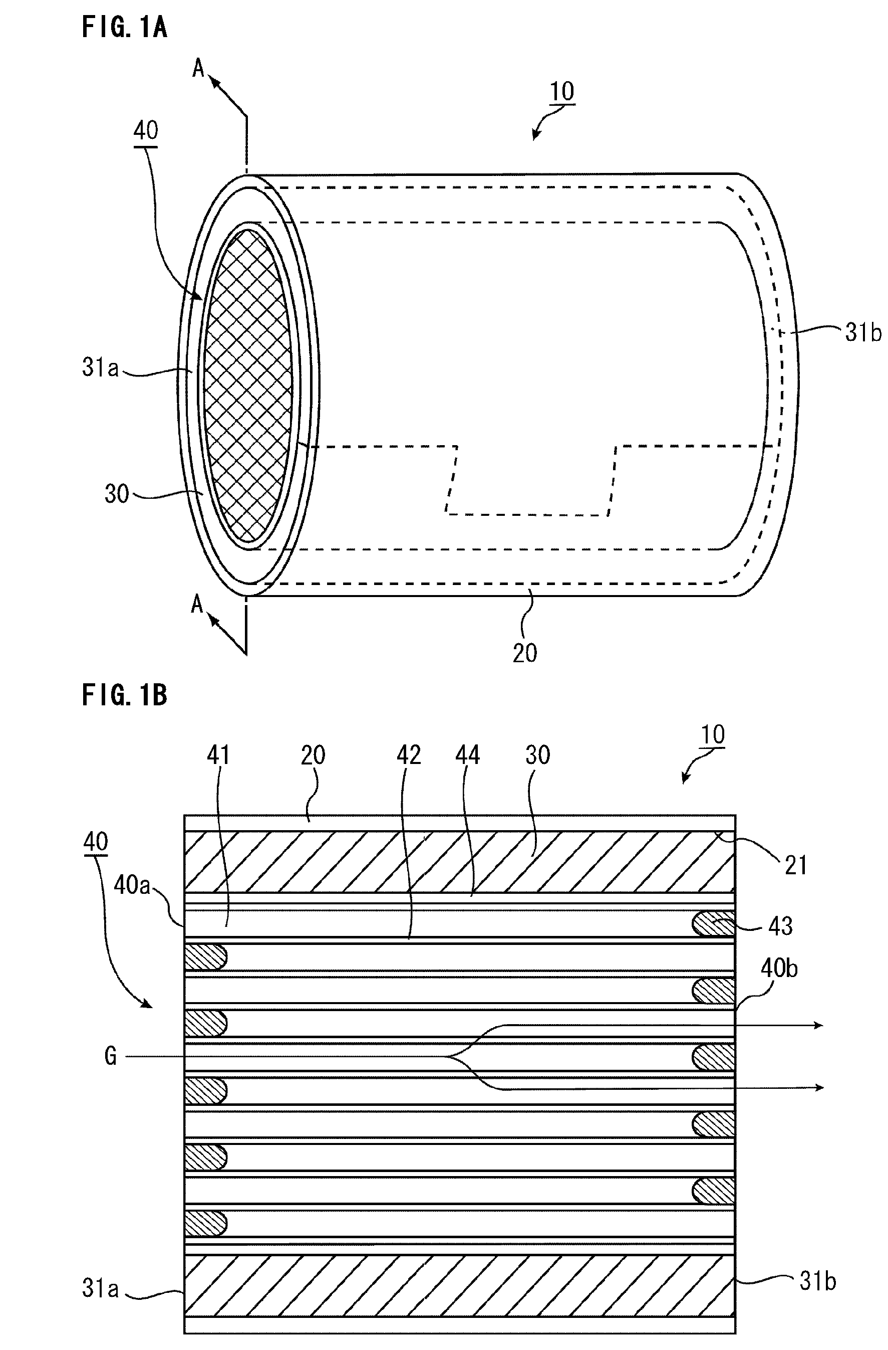
[0054]FIG. 1A is a perspective view schematically illustrating an exhaust gas purifying apparatus of the present embodiment, and FIG. 1B is an A-A line cross-sectional view of the exhaust gas purifying apparatus illustrated in FIG. 1A.

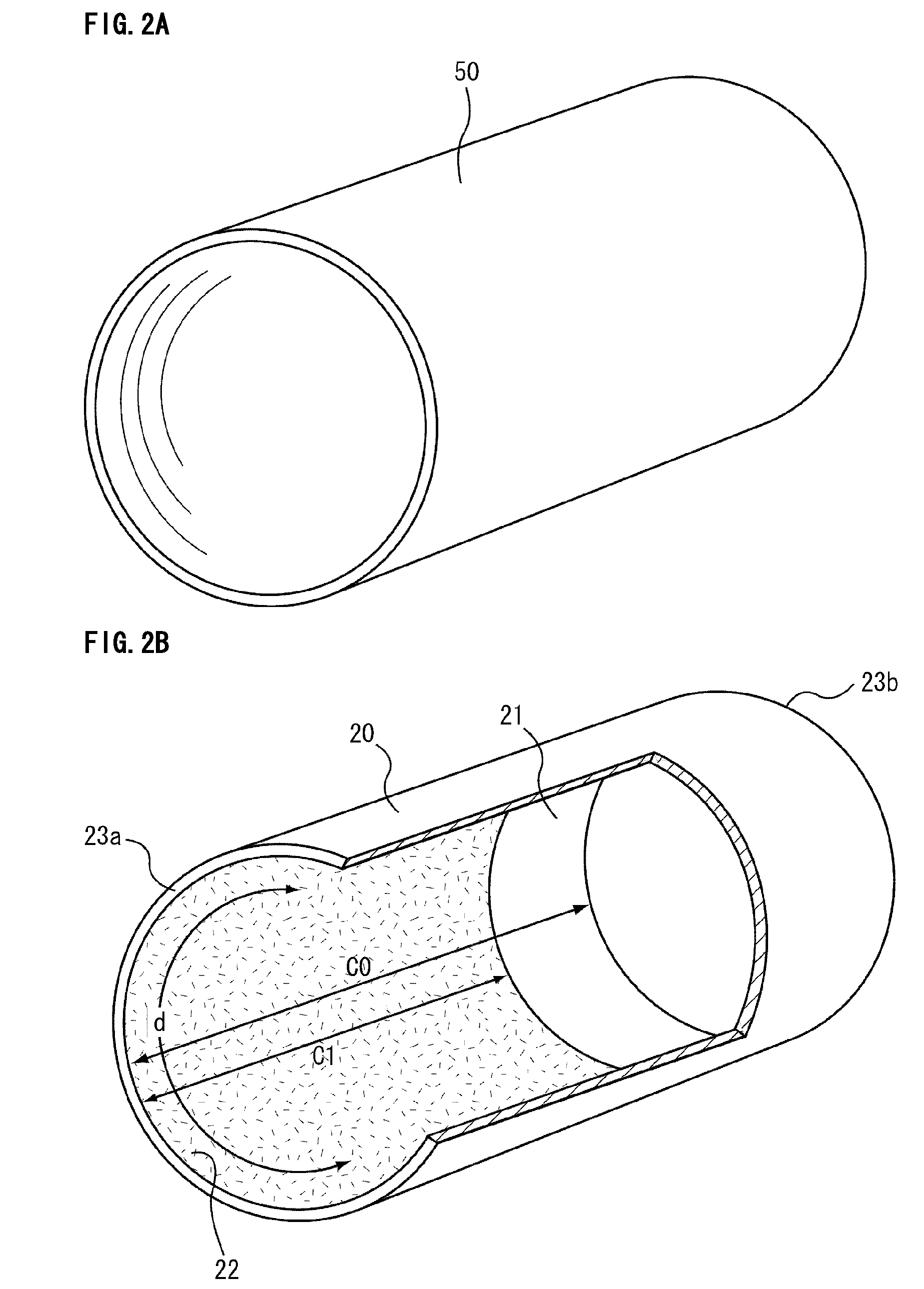
[0055]As illustrated in FIG. 1A and FIG. 1B, an exhaust gas purifying apparatus 10 includes: a pillar-shaped exhaust gas treating body 40 in which a large number of cells 41 are longitudinally disposed in parallel with one another with a cell wall 42 interposed therebetween; a metal casing 20 housing the exhaust gas treating body 40; and a holding sealing material 30 provided between the exhaust gas treating body 40 and the metal casing 20 and configured to hold the exhaust gas...

example 1

(1) Manufacture of a Holding Sealing Material

[0110]A base mat having a compounding ratio of Al2O3:SiO2=72:28 was prepared as a base mat including alumina fibers having an alumina-silica composition. The needle treating mat having a bulk density of 0.15 g / cm3 and a weight per square meter of 1050 g / m2 was manufactured by carrying out needling treatment on this base mat.

[0111]Separately, an acrylic latex emulsion in which an acrylic latex is dispersed in water was prepared and this was used as a binder solution.

[0112]Next, the needle treating mat was cut into a size of 265 mm×83 mm in a plan view. The binder solution was sprayed evenly over the cut needle treating mat by using a spray so as to give 1.0% by weight of the binder with respect to the amount of alumina fibers in the cut needle treating mat, so that the binder solution was allowed to adhere to the mat.

[0113]Then, the needle treating mat with the binder solution adhered thereto was dried by through air at 140° C. under the p...

second embodiment

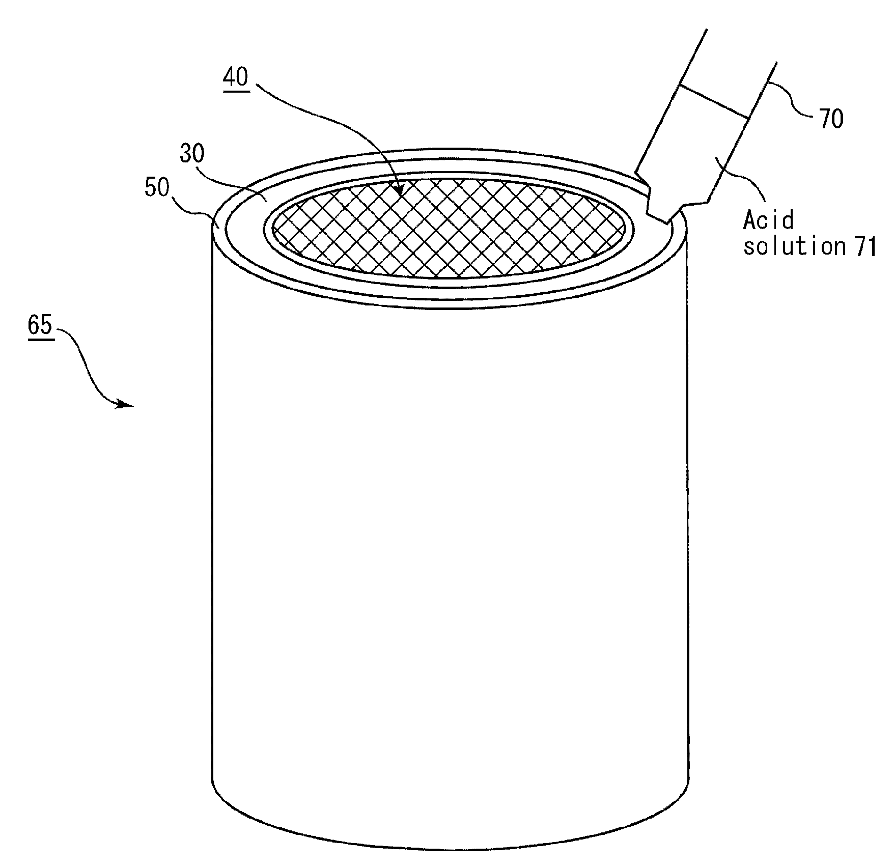
[0130]In the exhaust gas purifying apparatus of the present embodiment, the corrosion area is formed by a chloride solution, not by hydrochloric acid.

[0131]Hereinafter, an exhaust gas purifying apparatus in which the corrosion area is formed by a chloride solution containing sodium chloride as a chloride, and a method for manufacturing an exhaust gas purifying apparatus are described.

[0132]The exhaust gas purifying apparatus of the present embodiment has a similar configuration as the exhaust gas purifying apparatus of the first embodiment, except that the corrosion area is formed by sodium chloride solution.

[0133]The degree of the corrosion of the casing base depends on the concentrations of sodium chloride solution and hydrochloric acid. Here, since sodium chloride solution has the lower corrosivity than hydrochloric acid, the degree of the corrosion by sodium chloride solution is generally smaller than that by hydrochloric acid when they have the same mol concentration.

[0134]In t...


PUM

PropertyMeasurementUnit
lengthaaaaaaaaaa
diameteraaaaaaaaaa
pressureaaaaaaaaaa

Abstract

An exhaust gas purifying apparatus includes an exhaust gas treating body, a metal casing, and a holding sealing material. The exhaust gas treating body has a longitudinal direction and includes cell walls extending along the longitudinal direction to define cells between the cells. The metal casing has an inner surface and houses the exhaust gas treating body to face the inner surface. The holding sealing material is provided between the exhaust gas treating body and the inner surface of the metal casing to hold the exhaust gas treating body in the metal casing. The holding sealing material includes an inorganic fiber aggregated body. The metal casing has a corrosion area at least on a part of the inner surface. The corrosion area includes a corroded base material of the metal casing.

Description

CROSS-REFERENCE TO RELATED APPLICATIONS[0001]The present application claims priority under 35 U.S.C. §119 to Japanese Patent Application No. 2009-070768, filed on Mar. 23, 2009, the contents of which are incorporated herein by reference in their entirety.BACKGROUND OF THE INVENTION[0002]1. Field of the Invention[0003]The present invention relates to an exhaust gas purifying apparatus and a method for manufacturing an exhaust gas purifying apparatus.[0004]2. Discussion of the Background[0005]Particulate matters (hereinafter, also referred to as PMs) are contained in exhaust gases discharged from internal combustion engines such as diesel engines, and in recent years, there has arisen a serious problem that these PMs are harmful to the environment and the human bodies. Moreover, since exhaust gases also contain toxic gas components such as CO, HC, and NOx, there have been growing concerns about influences of these toxic gas components on the environment and the human bodies.[0006]In v...

Claims


Application Information

Patent Timeline
Patent Type & Authority Patents(United States)
IPC IPC(8): B01D50/00
CPCF01N3/2853F01N2310/06F01N2350/00F01N2450/00F01N2450/02Y10T29/49826F01N2310/00Y10T29/49345F01N2510/00
Inventor MITANI, KENICHIEGUCHI, MASAYUKIYANAGISAWA, TATSUNARI
Owner IBIDEN CO LTD
Why Eureka
Try Eureka