
Algorithmic reduction of vehicular magnetic self-noise

a technology of vehicular magnetic and self-noise, applied in the field can solve the problems of conventional approach being inadequate for any application, affecting the success of magnetic anomaly detection, and affecting the detection of magnetic anomalies

Inactive Publication Date: 2013-03-05
THE UNITED STATES OF AMERICA AS REPRESENTED BY THE SECRETARY OF THE NAVY
View PDF12 Cites 10 Cited by
  • Summary
  • Abstract
  • Description
  • Claims
  • Application Information

AI Technical Summary

Benefits of technology

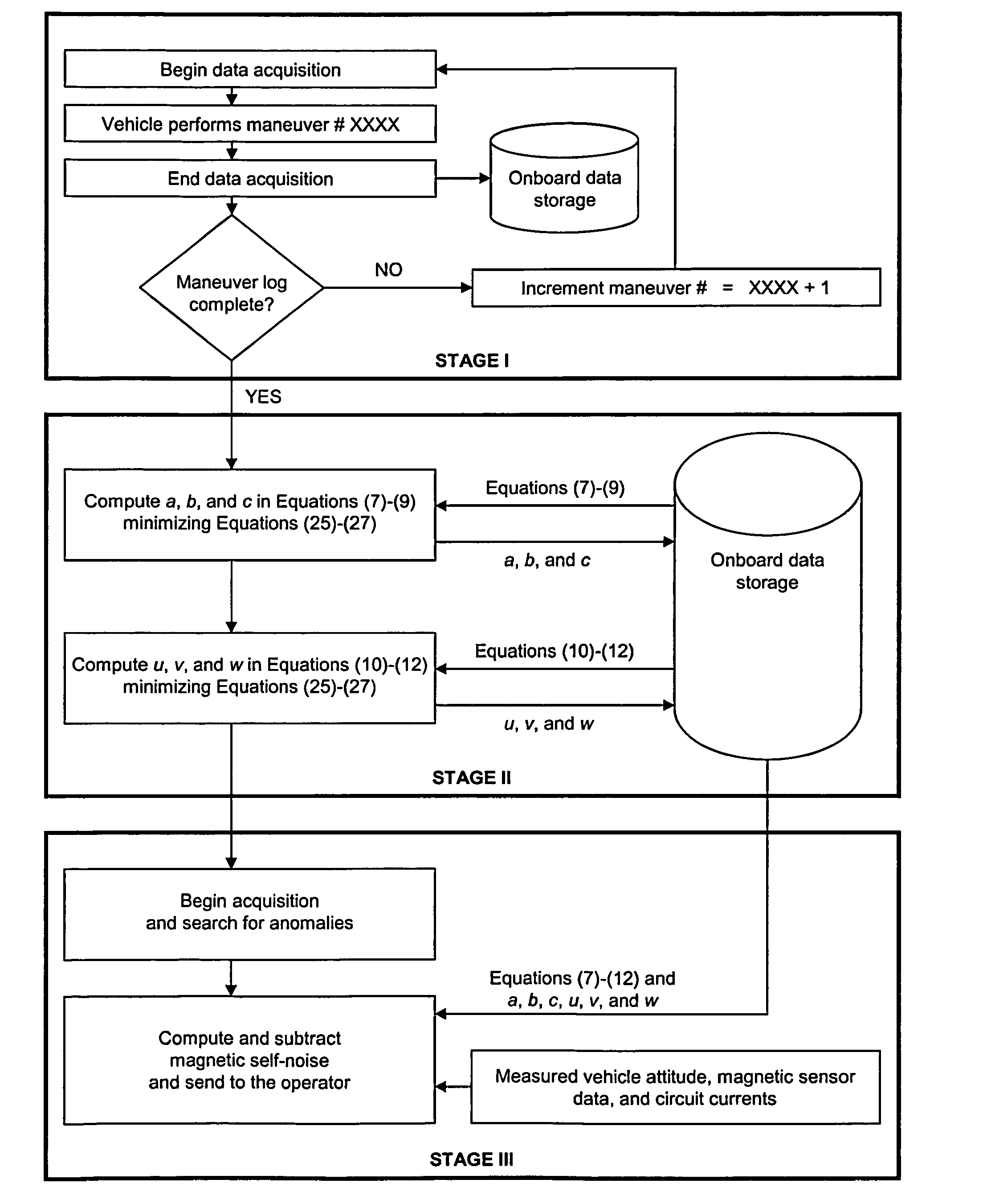
The present invention improves the accuracy of detecting magnetic anomalies by reducing the magnetic noise of underwater vehicles that are used for this purpose. This is achieved by more accurately reducing the magnetic self-noise of the vehicle itself. This invention is especially useful in applications where the sensor conveyance vehicle is close to a different vehicle that serves some operational purpose and the central control vehicle is tethered to the sensor conveyance vehicle. This invention also affords improved self-noise reduction with respect to finding certain mathematical solutions in self-noise reduction contexts in general.

Problems solved by technology

The successful detection of magnetic anomalies can be significantly compromised by vehicular magnetic self-noise, i.e., magnetic noise emanating from the vehicle itself that houses and conveys the magnetic sensing instrumentation.
However, the conventional approach may be inadequate for any application in which anomalous magnetic circumstances exist in the vicinity of and external to the sensor conveyance vehicle, because the conventional approach does not account for these other extrinsic magnetic anomalies.

Method used


Image

  • Algorithmic reduction of vehicular magnetic self-noise
  • Algorithmic reduction of vehicular magnetic self-noise
  • Algorithmic reduction of vehicular magnetic self-noise

Examples


Embodiment Construction

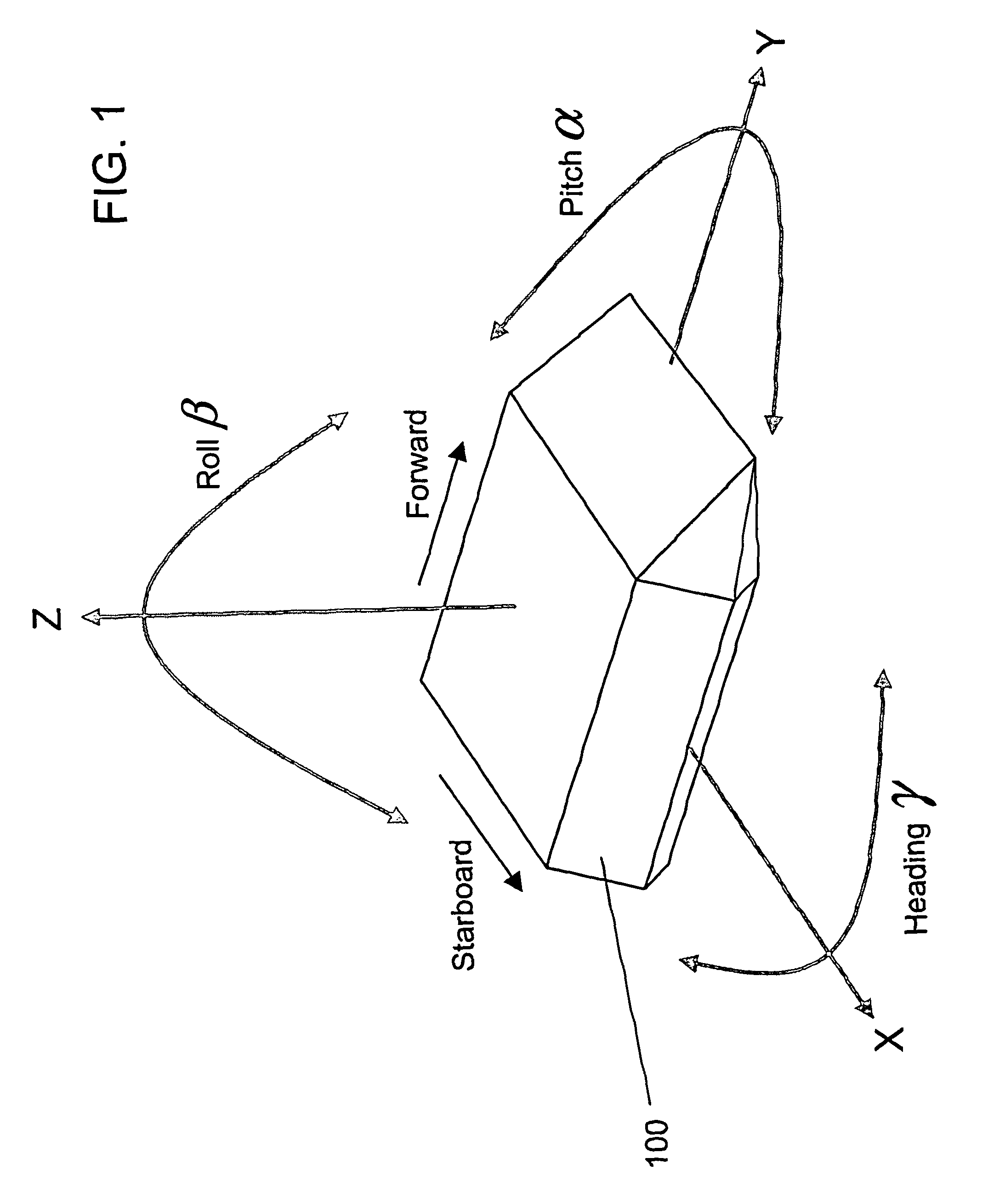
[0025]Mathematical characterization of vehicular magnetic self-noise begins with a decomposition of the vehicular magnetic self-noise in accordance with magnetic source. A vehicle has three main sources of magnetization that contribute to its self-noise. These three magnetic sources are (i) induced magnetization (“IM”), (ii) permanent magnetization (“PM”), and (iii) stray fields (“Stray”). The term “induced magnetization” as used herein generally refers to the distortion of the earth's ambient magnetic field through the ferromagnetic material of onboard objects. The term “permanent magnetization” as used herein generally refers to the magnetic fields produced by ferromagnetic materials of onboard objects. The term “stray fields” as used herein generally refers to magnetic fields created by electrical currents in onboard circuitry.

[0026]With reference to FIG. 1, a Cartesian coordinate system is assumed for the three-dimensional space of interest, which contains the magnetic anomaly d...


PUM


Abstract

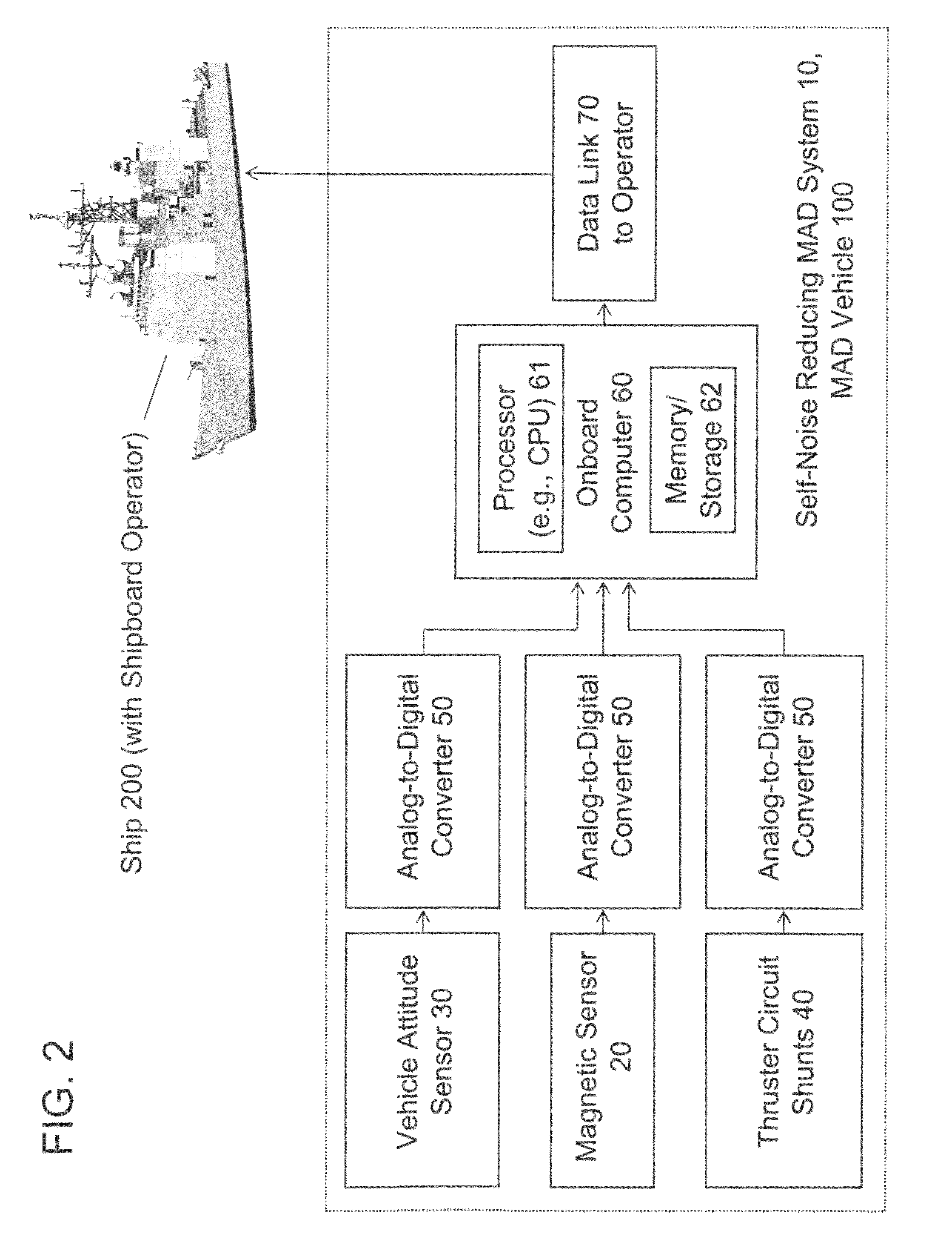
Removal of extraneous magnetic measurement components from magnetic anomaly detection (MAD) tends to increase its accuracy. Conventional removal accounts for anomalous magnetism manifested by the MAD vehicle (typically, unmanned), but assumes that the magnetic field applied to the MAD vehicle is the earth's magnetic field, i.e., is non-anomalous and known. In contrast, the present invention accounts not only for anomalous magnetism manifested by the MAD vehicle, but also for anomalous magnetism manifested in the MAD vehicle's vicinity, such as by a manned control vehicle. The present invention's mathematical characterization of vehicular “self-noise” due to induced and permanent magnetization is more refined, especially insofar as treating the vehicle's ambient magnetic field as an unknown (empirical) quantity, rather than a known (non-empirical) quantity. A typical inventive system for vehicular magnetic self-noise-reduced magnetic anomaly detection includes magnetic and other sensors, and a computer implementing the inventive mathematical characterization in processing the signals.

Description

BACKGROUND OF THE INVENTION[0001]The present invention relates to magnetic anomaly detection, more particularly to methods, systems, and devices for offsetting, compensating, or counterbalancing magnetic noise associated with vehicles used to carry or deploy magnetic anomaly detectors such as magnetometers and gradiometers.[0002]Magnetic anomaly detection (“MAD”) has been practiced in geological, military, and other applications, such as involving detection of ore or mineral deposits, shipwrecks, enemy submersibles, etc. According to conventional practice of magnetic anomaly detection, the magnetic anomaly detection vehicle is an unmanned vehicle equipped with a magnetic field sensor (e.g., magnetometer) or a magnetic gradient sensor (e.g., gradiometer). The unmanned vehicle is commonly either an unmanned aerial vehicle (e.g., a “UAV”) or an unmanned underwater vehicle (e.g., an “ROV” or a “UUV”), and can be either autonomous or remotely controlled / operated (such as by radio signals...

Claims


Application Information

Patent Timeline
Patent Type & Authority Patents(United States)
IPC IPC(8): G01D18/00G01R33/02
CPCG01R33/022G01D3/036
Inventor CONNER, CHRISTOPHER I.HOLMES, JOHN J.PUGSLEY, DONALD E.
Owner THE UNITED STATES OF AMERICA AS REPRESENTED BY THE SECRETARY OF THE NAVY
Learn More