
Antenna module and electronic device using the same

an antenna module and electronic device technology, applied in the structure of radiating elements, elongated active elements, resonance antennas, etc., can solve the problems of reducing the energy transmission efficiency of the antenna, the unfavorable light of conventional antennas, and the poor signal reception quality of the antenna, so as to improve the area needed by the antenna module is reduced, and the effect of improving the radiation efficiency of the antenna

Active Publication Date: 2013-03-12
PEGATRON
View PDF6 Cites 0 Cited by
  • Summary
  • Abstract
  • Description
  • Claims
  • Application Information

AI Technical Summary

Benefits of technology

The solution effectively reduces the antenna's volume by over 40% and enhances radiation efficiency to cover four frequency bands (GSM900, DCS, PCS, WCDMA) with greater than 60% efficiency, minimizing interference from metal components.

Problems solved by technology

Therefore, metal electronic components, such as a camera, a speaker, a vibrator and so on, are disposed under the antenna, and the metal electronic components may interfere with the antenna, such that signal reception quality of the antenna may also become worse due to a bad environment of the antenna.
However, since a capacitance effect can be generated between the metal ground surface element 101 and the radiation conductor element 102, and a capacitor can store energy, the capacitance effect can reduce the energy transmission efficiency of the antenna such that a part of the energy is stored by the capacitor and the energy cannot be wholly radiated out.
Therefore, the conventional antenna is unfavorable for light, slim, short, and small development of the cell phone.
Besides, since the size of the antenna is great, the metal electronic components may fail to keep away from the antenna thus to interfere with the antenna and to affect the signal reception quality.

Method used


Image

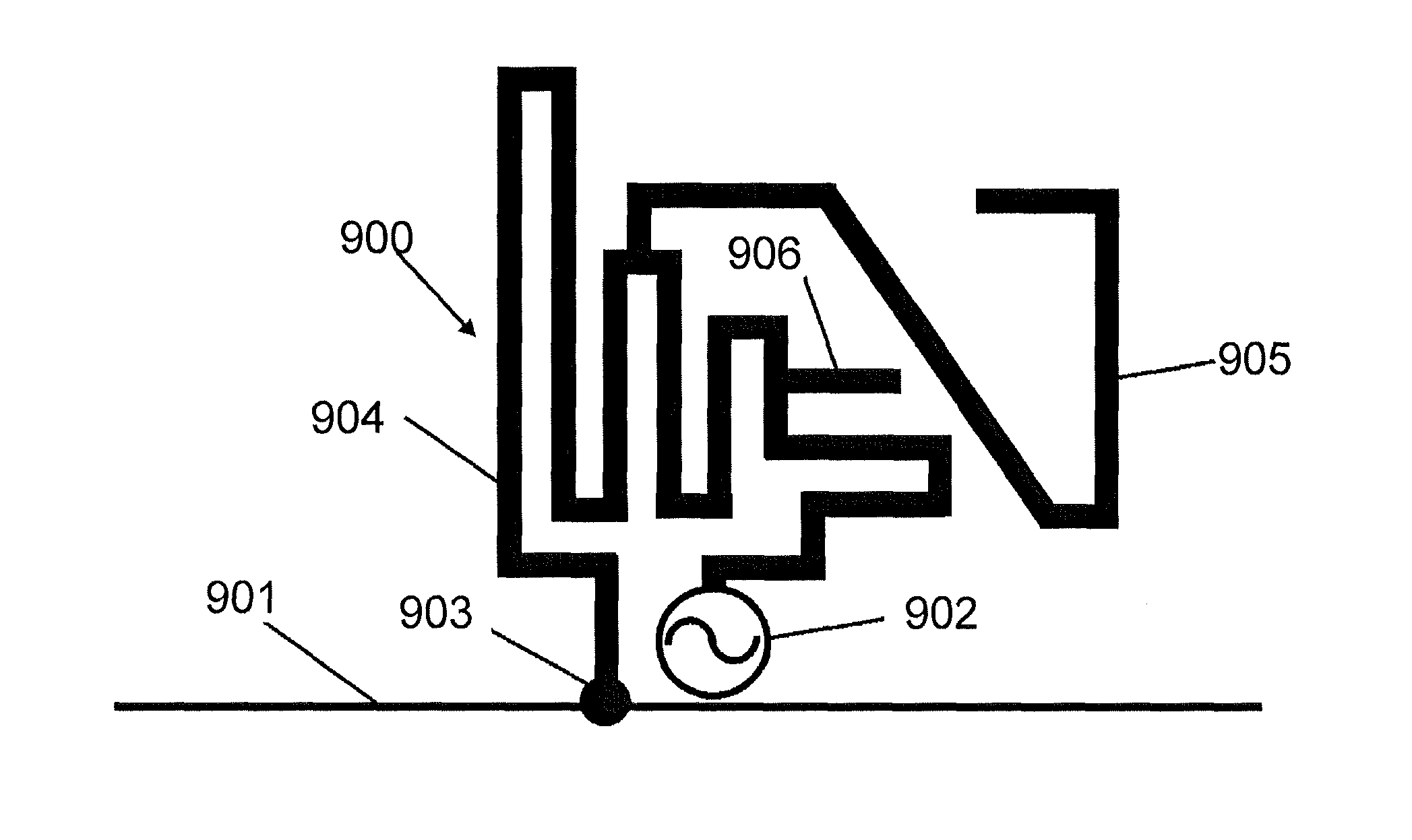
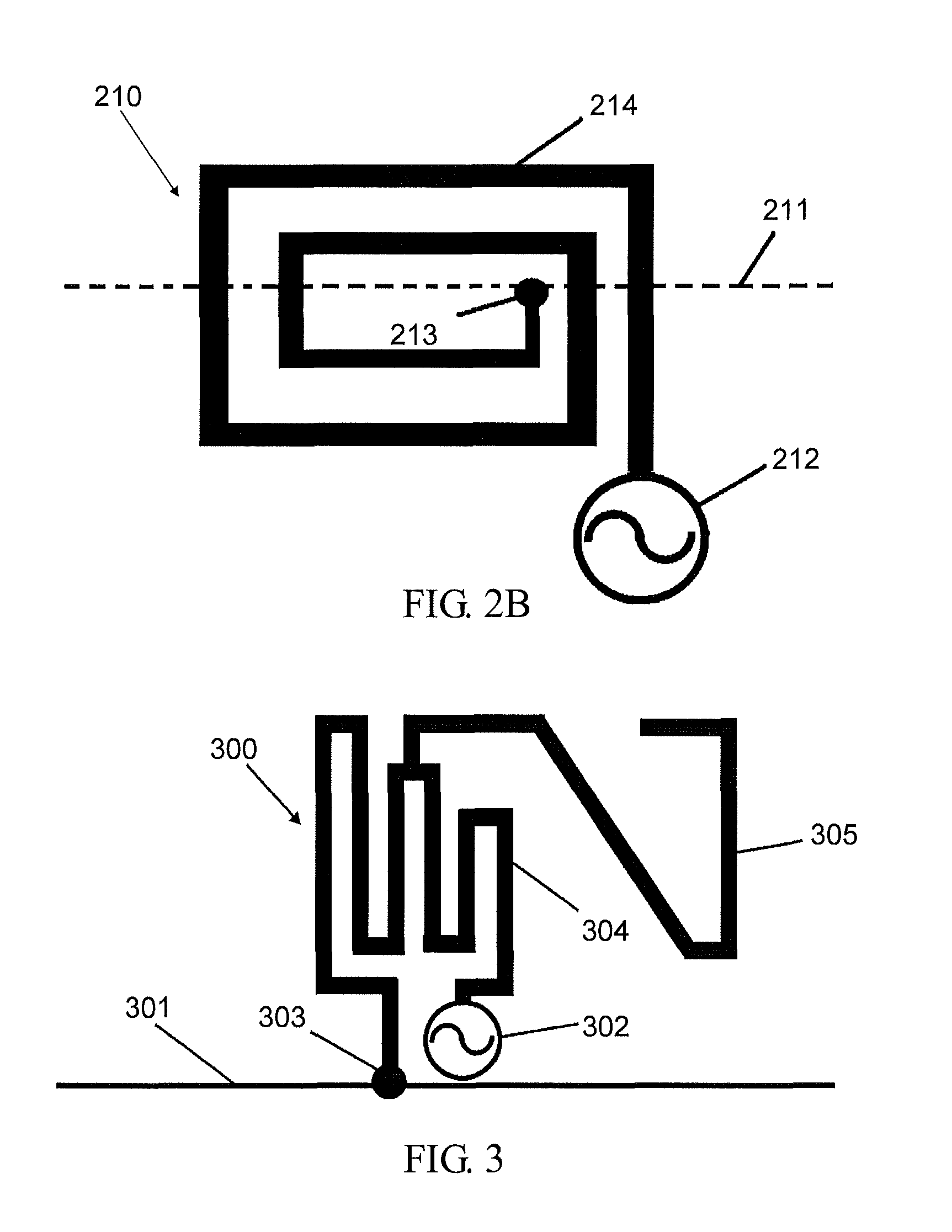
  • Antenna module and electronic device using the same
  • Antenna module and electronic device using the same
  • Antenna module and electronic device using the same

Examples


Embodiment Construction

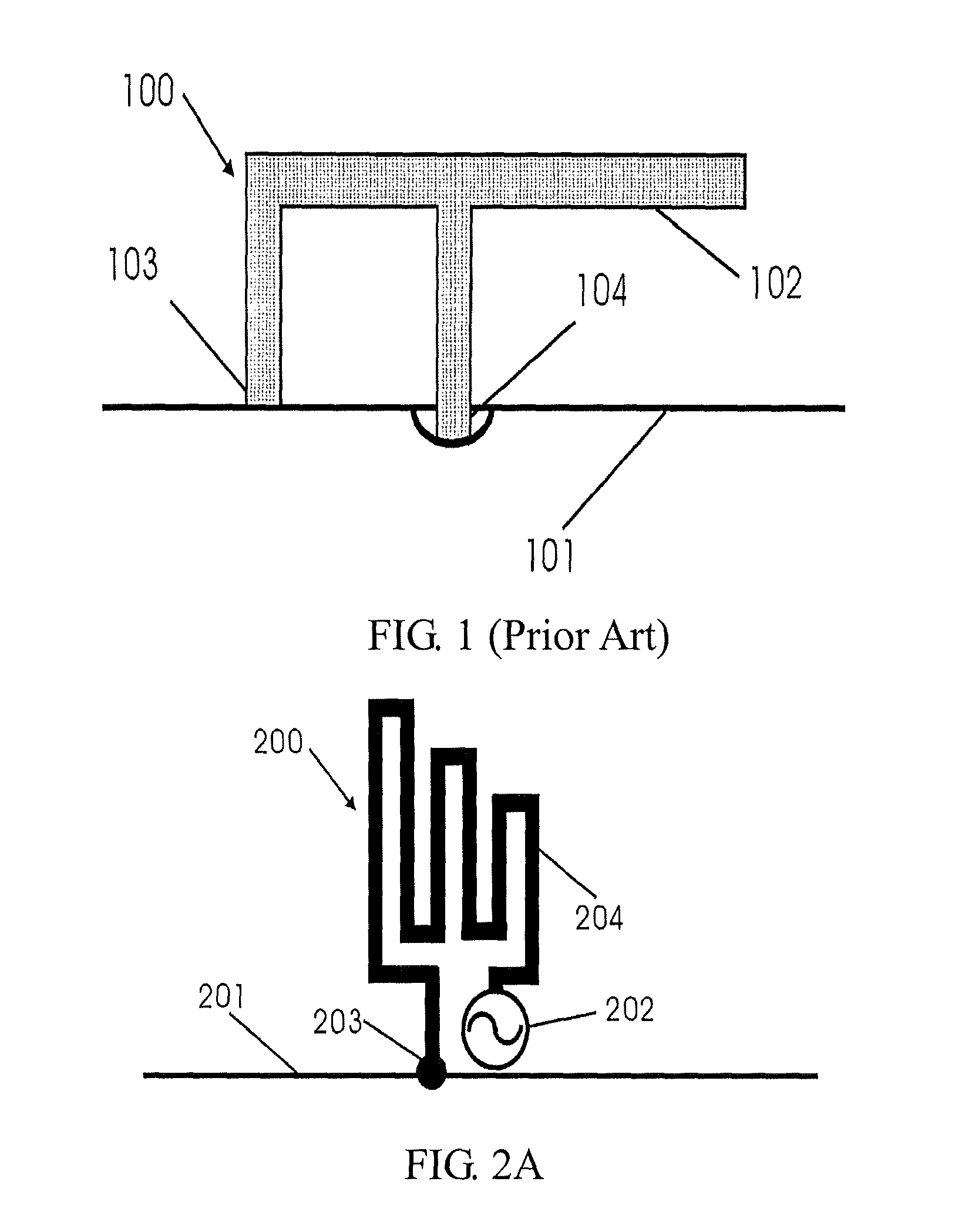
[0032]First, please refer to FIG. 2A. FIG. 2A is a planar diagram showing an antenna module 200 according to one embodiment of the invention. The antenna module 200 includes a metal ground surface 201, a signal feeding part 202, a ground part 203, and a first asymmetric meander line 204. The ground part 203 is connected with the metal ground surface 201, and the ground part 203 can be a short-circuit wire. One terminal of the first asymmetric meander line 204 is connected with the signal feeding part 202, the other terminal of the first asymmetric meander line 204 is connected with the ground part 203, and the first asymmetric meander line 204 does not meander toward its inner side.

[0033]The first asymmetric meander line 204 can allow the area needed by the antenna module 200 to be reduced and can generate an inductive effect thus to counteract an existent capacitance effect of the antenna module 200, thereby improving antenna radiation efficiency. In the embodiment, a signal is fed...


PUM


Abstract

This invention provides an antenna module and an electronic device using the same. The antenna module includes a signal feeding part, a ground part, and a first asymmetric meander line. One terminal of the first asymmetric meander line is connected with the signal feeding part, the other terminal is connected with the ground part, and the first asymmetric meander line does not meander toward its inner side. A signal is fed in via the signal feeding part to allow the first asymmetric meander line to excite a first resonance frequency. An area of the antenna module in the invention is smaller than that of a conventional planar antenna, and the antenna module can generate an inductive effect to improve antenna radiation efficiency. Besides, since the area of the antenna module is small, a metal electronic component in the electronic device and the antenna module won't overlap thus to reduce interference.

Description

CROSS-REFERENCE TO RELATED APPLICATIONS[0001]This Non-provisional application claims priority under 35 U.S.C. §119(a) on Patent Application No(s). 098127291 filed in Taiwan, Republic of China Aug. 13, 2009, the entire contents of which are hereby incorporated by reference.BACKGROUND OF THE INVENTION[0002]1. Field of the Invention[0003]This invention relates to an antenna module and an electronic device using the same and, more particularly, to an antenna module with a small area and an electronic device using the same.[0004]2. Description of the Related Art[0005]In recent years, with fast development of global handheld wireless communications industry, cell phones are developed from dual-band (such as a global system for mobile communications 900 (GSM900) / a digital cellular system (DCS)) cell phones with a simple telephoning function in an early period to tri-band (such as GSM900 / DCS / personal communications service (PCS)) and even to quad-band (such as GSM900 / DCS / PCS / wideband code d...

Claims


Application Information

Patent Timeline
Patent Type & Authority Patents(United States)
IPC IPC(8): H01Q1/38H01Q1/36H01Q5/10
CPCH01Q9/42H01Q1/243H01Q9/0421H01Q9/0442
Inventor HUANG, CHIN-TING
Owner PEGATRON
Learn More