

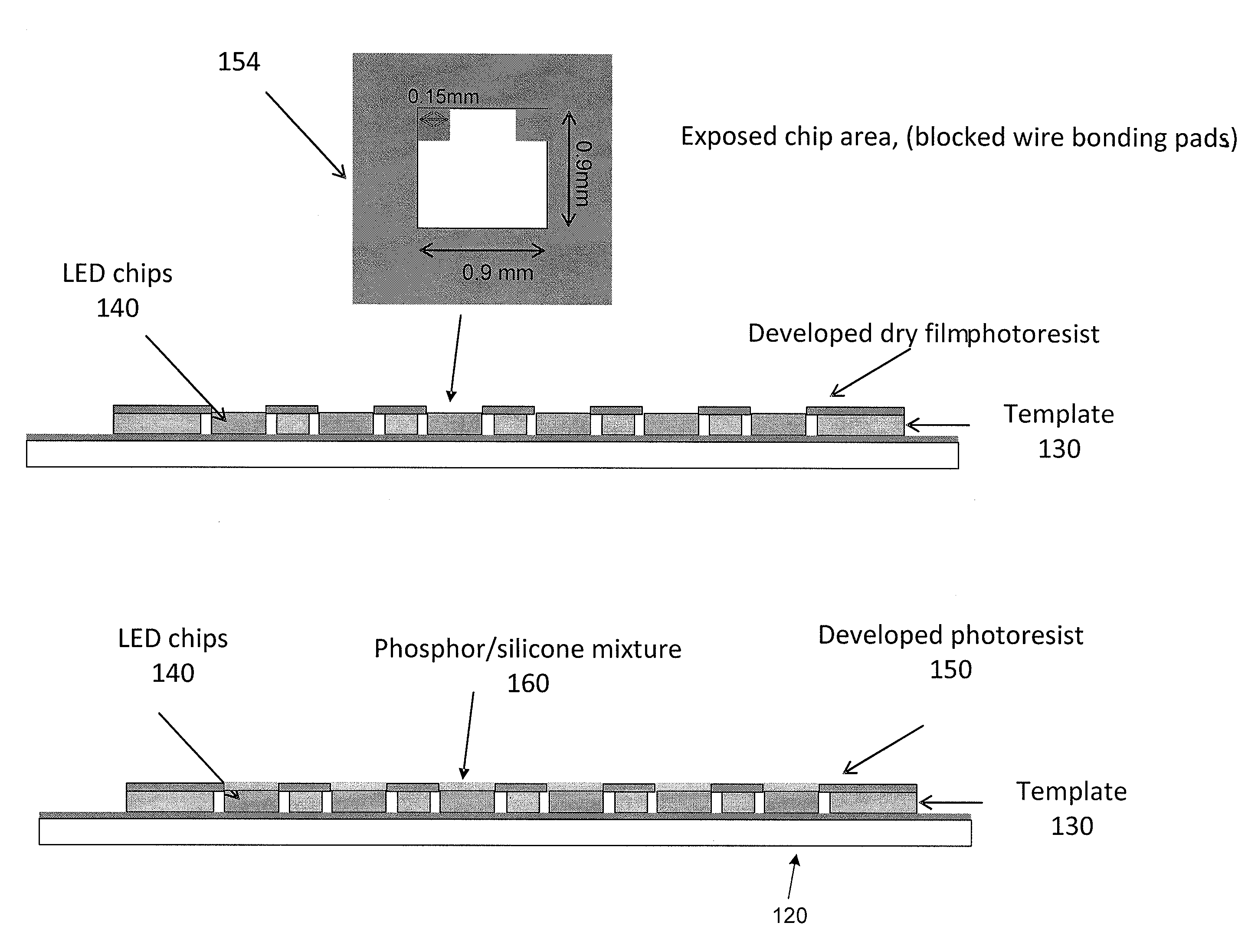
Deposition of phosphor on die top using dry film photoresist
- Summary
- Abstract
- Description
- Claims
- Application Information
AI Technical Summary
Benefits of technology
Problems solved by technology
Method used
Image

Examples
Embodiment Construction
[0024]The description below will be made with reference to a series of drawing figures enumerated above. These diagrams are merely an example, which examples, and should not unduly limit the scope of the claims herein. In connection with the various aspects illustrated and described, one of ordinary skill in the art would recognize other variations, modifications, and alternatives.
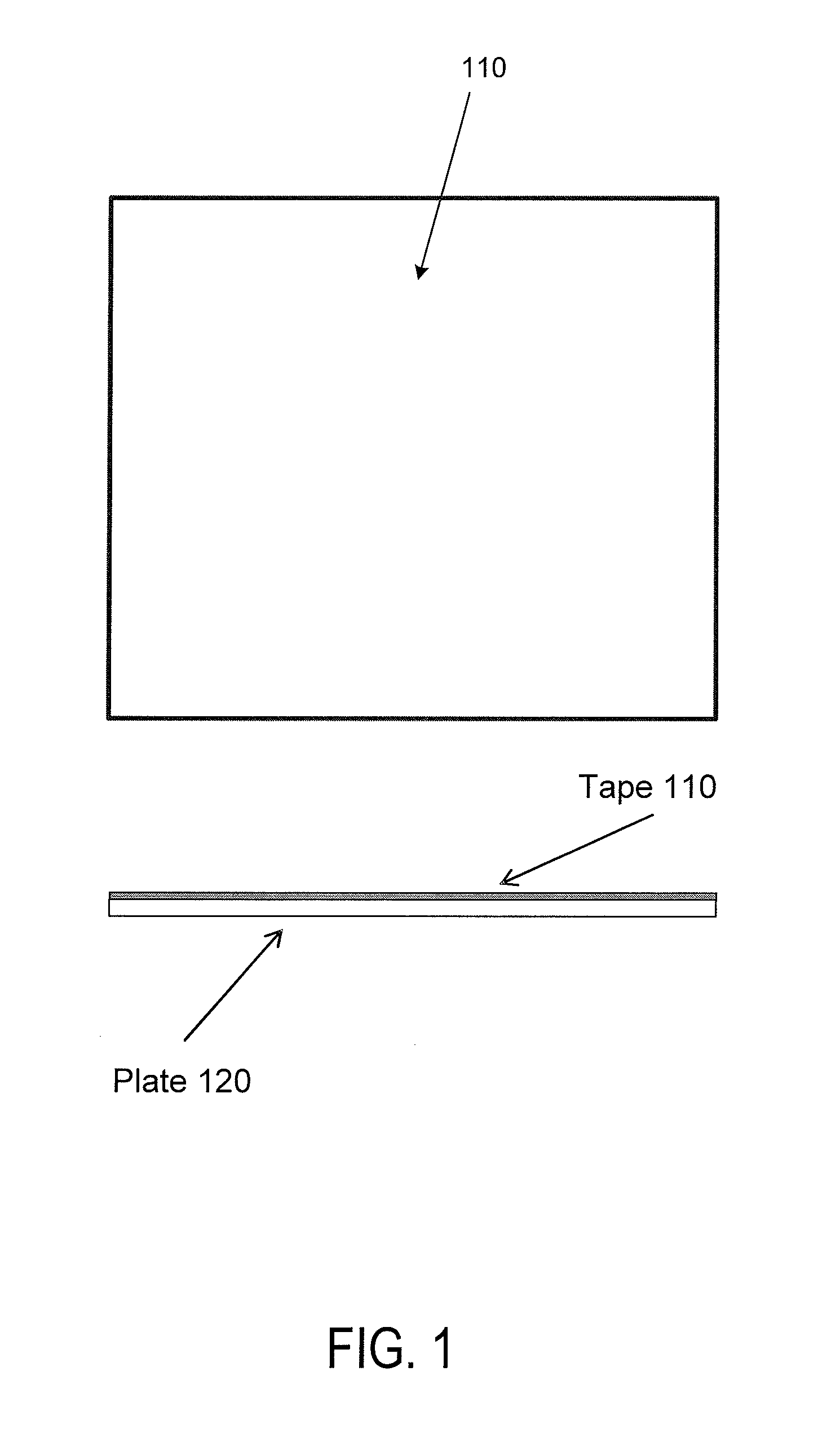
[0025]FIG. 1 shows a top view and a cross-sectional view of a substrate for carrying out the method for phosphor deposition. An adhesive tape 110 is disposed on a glass plate 120. In an embodiment, the tape a double-sided adhesive tape, which can be a thermal release or a UV release tape made of, e.g., polyester. For example, a commercially available tape from Semiconductor Equipment Corp. can be used. Tape 110 is attached to plate 120 the glass substrate. In a specific embodiment, plate 120 is about 1 mm thick. But plates having other suitable thicknesses can also be used.
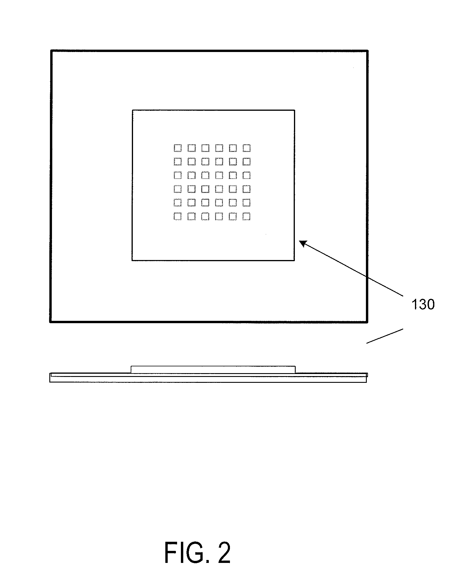
[0026]In FIG. 2, a grid template ...
PUM
 Abstract
Description
Claims
Application Information