Systems and methods for improving catheter hole array efficiency

a technology of catheter hole array and efficiency improvement, which is applied in the direction of metal-working equipment, catheters, metal-working equipment, etc., can solve the problems of high pressure within the infusion system, failure of the infusion system components, and undesirable acceleration of infused fluid, so as to achieve faster and more efficient rapid infusion procedures

Active Publication Date: 2013-03-26
BECTON DICKINSON & CO
View PDF54 Cites 38 Cited by
  • Summary
  • Abstract
  • Description
  • Claims
  • Application Information

AI Technical Summary

Benefits of technology

[0011]The systems and methods of the present disclosure have been developed in response to problems and needs in the art that have not yet been fully resolved by currently available infusion systems and methods. Thus, these systems and methods are developed to provide for safer and more efficient rapid infusion procedures.
[0013]In some embodiments, a tip portion of the intravenous catheter is modified to include a plurality of diffusion holes. The tip portion generally comprises a tapered profile, wherein the outer and inner surface of the tip taper towards the distal end of the catheter. The tapered outer surface provides a smooth transition between the narrow diameter of the catheter tip opening and the larger diameter of the catheter tubing. Thus, as the tip of the catheter is introduced into the vein of a patient, the tapered outer surface facilitates easy insertion of the catheter through the access hole. The tapered inner surface is generally provided to tightly contact the outer surface of an introducer needle housed within the lumen of the catheter. The introducer needle is provided to create an opening into the vein of patient through which the catheter tip is inserted. The tapered inner surface ensures a tight seal between the inner surface of the catheter and the outer surface of the needle. Following placement of the catheter, the introducer needle is removed.
[0014]As an infusant passes through the tapered portion of the inner surface, the fluid flow of the infusant is accelerated due to the decreased volume through the tapered tip. Thus, in some embodiments a plurality of diffusion holes are formed through the wall thickness of the intravenous catheter so as to provide a plurality of pathways through the wall of the intravenous catheter. Thus, as infusant flows through the catheter toward the tip of the catheter, a portion of the bulk flow through the catheter is diverted through the diffusion holes rather than through the main opening of the catheter tip. As such, the pressure within the infusion system is reduced as compared to systems incorporating standard intravenous catheter. Additionally, the plurality of diffusion holes reduce the jet velocity issued from the tip of the catheter, thereby enabling increased flow rates as required by some diagnostic procedures without additional damage to the vein wall.
[0015]In some embodiments, the diffusions holes are arranged on the catheter tip in a staggered array such that an upstream diffusion hole is unaligned with a downstream hole. As such, the fluid flow of an infusant that issues from a downstream diffusion hole is not disturbed by the fluid flow of an infusant that issues from an upstream diffusion hole. This feature provides increased flow efficiency through downstream diffusion holes.
[0017]In some embodiments, the diffusion holes are provided through the catheter wall at a predetermined bore angle. Specifically, the diffusion holes of the present invention include an inner wall surface that may be angled relative to the inner surface of the catheter lumen. In some embodiments, the inner surface of a diffusion hole is oriented to an acute angle relative to the inner surface of the catheter lumen. In other embodiments, an inner surface of the diffusion hole is oriented to an angle from about 15° to about 75° relative to the inner surface of the catheter lumen. In some embodiments, the bore angle of the diffusion hole is selected so as to optimize flow efficiency through the diffusion hole, catheter tension within the vein, centralized positioning of the catheter tip within the vein, and reduction of system pressure and tip jet velocity within an infusion system.

Problems solved by technology

Power injection procedures generate high pressures within the infusion system, thereby requiring specialized vascular access devices, extension sets, media transfer set, pump syringes, and bulk or pre-filled contrast media syringes.
Power injections of viscous media at this injection rate produce significant back pressure within the infusion system that commonly results in a failure of the infusion system components.
This acceleration of the infused fluid is undesirable for several reasons.
For example, the tapered catheter results in a greater backpressure for the remainder of the catheter assembly.
This effect is undesirable due to the limitations of the pumping capacity of the infusion pump as well as the limited structural integrity of the components and subcomponents of the infusion system.
For example, if the backpressure becomes too great, the pump's efficiency may decrease and certain seals or connections within the infusion system may fail.
Additionally, the fluid acceleration in the catheter tip results in a recoil force that may cause the catheter tip to shift within the patient's vein thereby displacing the catheter and / or damaging the patient's vein and / or injection site.
In some procedures, the fluid jet may pierce the patient's vein wall thereby leading to extravasation or infiltration.
Not only is this uncomfortable and painful to the patient, but infiltration may also prevent the patient from receiving the needed therapy.

Method used


Image

  • Systems and methods for improving catheter hole array efficiency
  • Systems and methods for improving catheter hole array efficiency
  • Systems and methods for improving catheter hole array efficiency

Examples


example 1

Tip Jet Velocity Comparison

[0051]The jet velocities at the tip of a standard catheter are in excess of 1,000 in / sec for a 5 ml / sec volumetric flow rate setting, which results in a large force applied to the vein wall of a patient. This force is treacherous for patients with non-optimal vein structure provisions increasing the likelihood of extravasation or intima damage with increasing flow rates.

[0052]Jet tip velocities of a standard 22 GA×1.00″ catheter (V_tip Current) were compared to a 22 GA×1.00″ catheter (V_tip Ex. 1−V_tip Ex. 4) modified to include a plurality of diffusion holes, as described in connection with FIGS. 4A and 4B, above. Quadruplicate samples of the modified catheter were tested at flow rates of 1 ml / sec, 2 ml / sec, 3 ml / sec, 4 ml / sec, and 5 ml / sec. Tip jet velocity was then recorded for each sample and compared to the jet velocity of the standard catheter at each flow rate. The experiment demonstrated that the overall tip jet velocity of the modified catheter wa...

example 2

System Pressure Comparison

[0053]Internal pressures within an infusion system were compared between an infusion system using a standard 22 GA×1.00″ catheter and an infusion system using a 22 GA×1.00″ catheter (P_inj #1 and P_inj #2) modified to include a plurality of diffusion holes, as described in connection with FIGS. 4A and 4B, above.

[0054]System pressure was measured both within each infusion pump (P_inj Current, P_inj 1 and P_inj 2) and the inner lumen of each catheter (P_sept Current, P_sept 1 and P_sept 2). System pressure was tested and recorded at flow rates of 1 ml / sec, 2 ml / sec, 3 ml / sec, 4 ml / sec, and 5 ml / sec. System pressures at each flow rate where then graphed, as shown in FIG. 6.

[0055]The results of the experiment demonstrate an increase in the volumetric flow rate by decreasing system pressure by nearly 30%, with the greatest reduction in pressure being shown within the lumen of the modified catheters.

example 3

Computational Fluid Dynamic Analysis

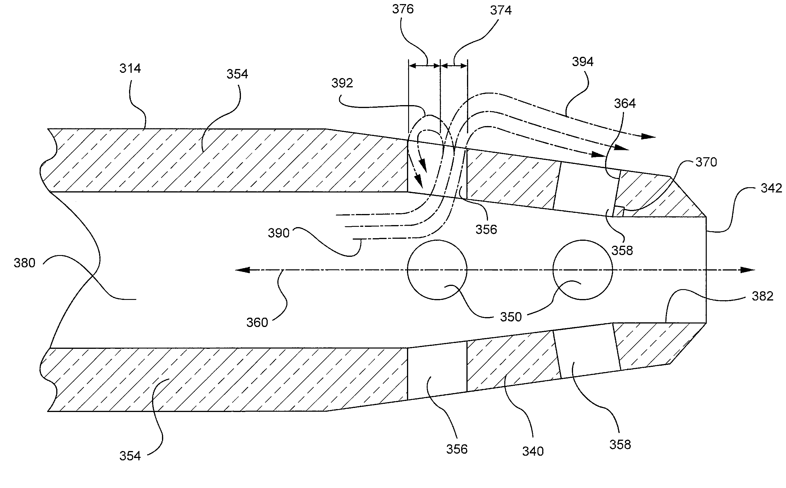
[0056]Computation fluid dynamic analysis was conducted on a standard 22 GA×1.00″ catheter modified to include a plurality of diffusion holes bored approximately 45° relative to the inner wall surface of the catheter. The analysis revealed an addition 6% diversion of bulk flow from the main stream into the diffusion holes, as compared to a standard 22 GA×1.00″ catheter having a plurality of diffusion holes bored 90° relative to the inner wall surface of the catheter. The analysis further revealed a significant increase in fluid flow 492 through the cross section of the diffusion hole 450, as compared to the straight holes of the standard catheter. While the diffusion holes 450 of the present invention did show a slight recirculation eddy 494, the recirculation eddy 494 was significantly weaker as compared to the circulation eddy 392 of the standard catheter. A representative rendering of the fluid flow 492 is shown in FIG. 4B.


PUM

PropertyMeasurementUnit
angleaaaaaaaaaa
internal pressuresaaaaaaaaaa
angleaaaaaaaaaa

Abstract

A peripheral catheter having a catheter tip diffuser for reducing an exit velocity of an infusant within the catheter. Pluralities of diffusion side holes are provided on the tip portion of the catheter. Some examples further include pluralities of annularly arranged, staggered diffusion holes provided on the tip portion of an intravenous catheter to streamline infusant issued from the diffusion holes. An inner surface of each diffusion hole is further angled relative to the inner surface of the catheter lumen such that an infusant within the lumen exits the catheter though the diffusion holes at an angle less than 90°.

Description

RELATED APPLICATIONS[0001]This application claims the benefit of U.S. Provisional Application No. 61 / 046,843, filed Apr. 22, 2008, entitled POWER PIVC HOLE ARRAY EFFICIENCY IMPROVEMENTS, which is incorporated herein by reference.BACKGROUND OF THE INVENTION[0002]The present invention relates generally to vascular infusion systems and components, including catheter assemblies and devices used with catheter assemblies. In particular, the present invention relates to systems and methods for improving catheter hole array efficiency to provide enhanced infusion flowrates, lower system pressures, and reduced catheter exit jet velocities.[0003]Vascular access devices are used for communicating fluid with the anatomy of a patient. For example, vascular access devices, such as catheters, are commonly used for infusing fluid, such as saline solution, various medicaments, and / or total parenteral nutrition, into a patient, withdrawing blood from a patient, and / or monitoring various parameters of...

Claims


Application Information

Patent Timeline
Patent Type & Authority Patents(United States)
IPC IPC(8): A61M25/00
CPCA61M25/0009A61M25/007Y10T29/49826A61M2025/0073
Inventor ADAMS, CHAD M.MCKINNON, AUSTIN JASON
Owner BECTON DICKINSON & CO
Why Eureka
Try Eureka