Methods of manufacturing and temperature calibrating a coriolis mass flow rate sensor

a technology of mass flow rate and temperature calibration, which is applied in the direction of liquid/fluent solid measurement, specific gravity measurement, machines/engines, etc., can solve the problems of normal operation conditions, cracking or otherwise degrading of the adhesive joint, and the integrity of the coupling of the tube to the metal base is not necessarily unyielding and unchanging

Active Publication Date: 2013-03-26
MALEMA ENG
View PDF8 Cites 12 Cited by
  • Summary
  • Abstract
  • Description
  • Claims
  • Application Information

AI Technical Summary

Benefits of technology

[0010]It is an aspect of the present invention to provide a method of fabricating a Coriolis flowmeter from an elastic polymeric material having flow sensitive element(s) integrally connected to a suitable mounting base (or manifold) of the same material free of mechanical joints or adhesives thereby providing an unyielding, fixed boundary condition for the vibrating sensitive element.
[0011]It is another aspect of the present invention to provide a method of fabricating a Coriolis flowmeter from an elastic polymeric material having a flow sensitive element integrally connected to a suitable mounting base (or manifold) of the same material free of adhesives or mechanical joints thereby avoiding differential thermal expansion / contraction that would otherwise undermine the integrity and reliability of the boundary condition at the ends of the vibrating flow sensitive element.
[0012]It is another aspect of the present invention to provide a method of fabricating a Coriolis flowmeter from an elastic polymeric material employing a flow sensitive element that does not use tubing thereby avoiding the additional processing steps such as annealing and etching thereby simplifying the flowmeter fabrication process.
[0013]It is another aspect of the present invention to provide a method of fabricating a Coriolis flowmeter from an elastic polymeric material and forming a flow sensitive element (and flow passageways therein) without using low-melting point fusible metal alloys that could permanently contaminate the flow passageway(s).
[0014]It is another aspect of the present invention to provide a method of fabricating a Coriolis flowmeter from an elastic polymeric material allowing the fabrication of a flow sensitive element with comparatively thin-walls and / or with relatively small diameter flow passageways therein.
[0015]It is yet another aspect object of the present invention to provide a method for calibrating a Coriolis flowmeter fabricated from any elastic material (metal or plastic) allowing for accurate temperature compensation of the flow sensitive element's spring constant over any useful operating temperature range of the flowmeter.

Problems solved by technology

However, a shortcoming of the '053 and '815 patents is that under normal operating conditions the integrity of the coupling of the tube to the metal base is not necessarily unyielding and unchanging.
Rather, it could deteriorate over time from continuous vibration of the tube causing the adhesive joint to crack or otherwise degrade.
Additionally, differential thermal expansion / contraction between the different materials of construction (e.g., the tube, the cyanoacrylate adhesive and the metal base) will impair the integrity of the coupling of the tube to the metal base creating an unstable boundary condition resulting in uncontrolled vibration characteristics to such an extent that performance of the device would be compromised.
However, these annealing and etching processes add cost and complexity to the fabrication of the flowmeter and may not necessarily yield tubing suitable for flowmeter fabrication on a consistent basis.
. . with the possible exception of a driver and pick offs, and case, the entirety of the flowmeter is formed by injection molding (emphasis added).” However, this method of fabrication presents significant problems and limitations.
When fabricating thin-wall or small diameter flow passageways (e.g., 4 mm diameter; wall thickness <2 mm) such melt temperatures and pressures will likely distort the comparatively narrow (and flexible) fusible metal core (possibly melting its surface) resulting in deformation and contamination of the flow passageways to such an extent that the device could be rendered unusable.
However, unlike a solid core (e.g., stainless steel), the comparatively soft fusible core could partially melt or abrade during the injection molding process allowing metal atoms to mix and become embedded within the injected plastic permanently contaminating the flow passageway rendering the device unsuitable for high-purity applications.
In plastic injection molding processes, it is generally recommended that molded features have a similar thickness because otherwise the molded part may not form properly.
However, a consequence of forming the entirety of the flowmeter by injection molding could result in structural and / or dynamic design limitations or compromises that could adversely affect and / or limit flowmeter performance.
However, comparable data (e.g., elastic modulus vs. temperature) for elastic polymers are generally not available or are published at very few temperatures.
Significantly, without such temperature compensation, the meter would not be usable in applications wherein the sensor temperature differs substantially from that at calibration.

Method used


Image

  • Methods of manufacturing and temperature calibrating a coriolis mass flow rate sensor
  • Methods of manufacturing and temperature calibrating a coriolis mass flow rate sensor
  • Methods of manufacturing and temperature calibrating a coriolis mass flow rate sensor

Examples


Embodiment Construction

[0026]The Figures (FIGS.) and the following description describe certain embodiments by way of illustration only. One skilled in the art will readily recognize from the following description that alternative embodiments of the structures and methods illustrated herein may be employed without departing from the principles described herein. Reference will now be made in detail to several embodiments, examples of which are illustrated in the accompanying figures. It is noted that wherever practicable similar or like reference numbers may be used in the figures and may indicate similar or like functionality.

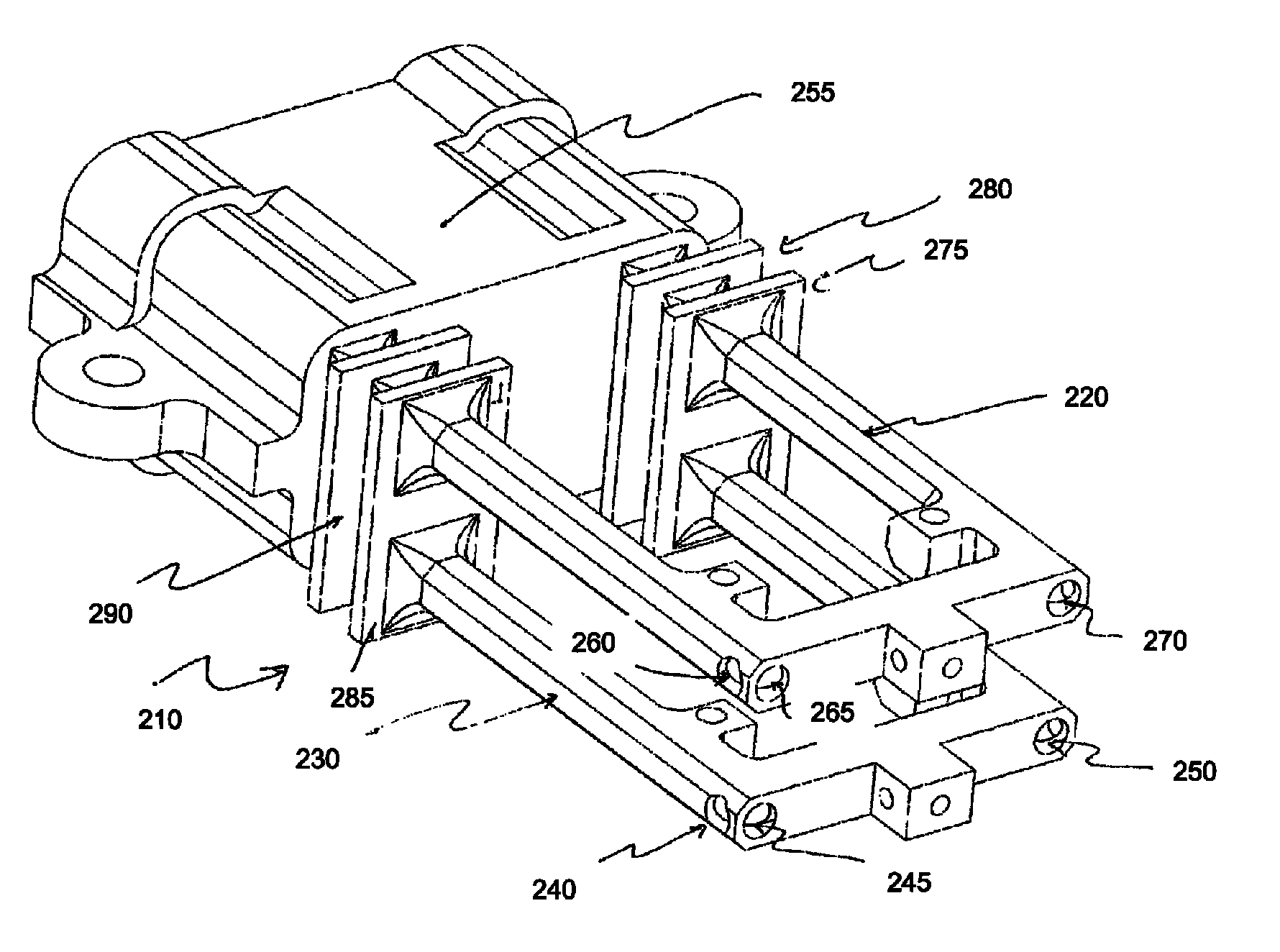
[0027]FIG. 1 illustrates a solid piece 110 of polymeric material, CNC-machined from a single block of elastic polymeric material, according to one embodiment. The flow-sensitive element of subassembly 110 is comprised of two square “U”-shaped assemblies 120 and 130. However, subassembly 110 is devoid of flow passageways to allow fluid to flow through the structure. Sub-assembly 110 c...


PUM

PropertyMeasurementUnit
melting pointaaaaaaaaaa
pressuresaaaaaaaaaa
temperaturesaaaaaaaaaa

Abstract

A subassembly of a Coriolis flowmeter is fabricated from a single monolithic piece of elastic polymeric material. The subassembly includes two flow-sensitive members and a base integrally connected to the two flow-sensitive members. The two flow-sensitive members include straight sections, and are substantially similar and parallel to each other. Flow passages are drilled along the straight sections of the two flow-sensitive members, and drilled entrances are sealed using the elastic polymeric material. A temperature sensor is fixedly attached to a flow-sensitive member for measuring a temperature of the flow-sensitive member and communicating the temperature to a metering electronics. The metering electronics determines a calibrated flow rate of fluid flowing through the Coriolis flowmeter that accounts for the temperature.

Description

CROSS REFERENCE TO RELATED APPLICATIONS[0001]This application claims the benefit of U.S. Provisional Application No. 61 / 304,228, “METHODS OF MANUFACTURING AND TEMPERATURE CALIBRATING A CORIOLIS MASS FLOW RATE SENSOR” by Alan M. Young, Jianren Lin, and Claus W. Knudsen, filed on Feb. 12, 2010, the content of which is hereby incorporated by reference in its entirety.FIELD OF THE INVENTION[0002]The present invention relates generally to fluid mass flow rate and density measuring apparatus based on the Coriolis-effect and in particular, methods for fabricating and calibrating an improved Coriolis flow rate sensor constructed from an elastic polymeric material (e.g., PFA—perfluoroalkoxy copolymer).DESCRIPTION OF PRIOR ART[0003]It is well known that Coriolis mass flowmeters can be used to measure the mass flow rate (as well as other properties) of a fluid flowing through a pipeline. Traditional Coriolis flowmeters employ various configurations of one or two tubes that are oscillated in a ...

Claims


Application Information

Patent Timeline
Patent Type & Authority Patents(United States)
IPC IPC(8): B29C47/00B32B38/04C08J5/00G01F1/84F02F1/06B29C65/00B29C67/24B32B37/00
CPCB29C67/004G01F1/8404G01F1/8418G01F1/8427G01F1/8431G01F1/8477G01F25/0007G01F1/8436B29K2021/00Y10T156/1056Y10T408/03Y10T409/303752Y10T29/49826Y10T29/4998G01F25/10G01N2009/006G01F1/84G01F15/02G01F25/00
Inventor YOUNG, ALAN M.LIN, JIANRENKNUDSEN, CLAUS W.
Owner MALEMA ENG
Why Eureka
Try Eureka