Microphone array

a microphone array and array technology, applied in the field of microphone arrays, can solve the problems of generating acoustic cavities, affecting the sound quality of the microphone, so as to simplify the processing of audio signals, improve the response uniformity, and simplify the effect of processing the captured audio signals

Active Publication Date: 2013-03-26
CRAVEN PETER G +2
View PDF9 Cites 40 Cited by
  • Summary
  • Abstract
  • Description
  • Claims
  • Application Information

AI Technical Summary

Benefits of technology

[0023]It is preferred that at least three of the axes of maximal sensitivity do not pass substantially through any point of symmetry of the plurality of microphone capsules. More preferably, none of the axes of maximal sensitivity pass substantially through any point of symmetry of the plurality of microphone capsules. Amongst other advantages, this reduces the tendency of the capsules to form an acoustic cavity.
[0047]In a further embellishment of the device, capsule in the first set may have attached to it a baffle arranged to reduce an asymmetry of disturbance caused by the capsule to the sound in the vicinity of the capsule. Thus the overall device may take account of its own impact on the sound field it is trying to capture.

Problems solved by technology

In particular, to obtain a second order output from zeroth order capsules will require 12 dB / 8 ve boost, as described in Rafaely, B., “Design of a Second-Order Soundfield Microphone”, Audio Eng. Soc. 118th Convention (Barcelona 2005), AES preprint #6405, although it is of doubtful practicality if a frequency range spanning several octaves is required.
However, in principle, these equations need to be solved separately for each required spherical harmonic output and for each frequency, thus requiring a large number of separately-specified equalisers.
This arrangement does however have a potential disadvantage, that of producing an acoustic cavity, as will now be explained.
The resonance can in principle be equalised, but it is hard to ensure that there will not be residual inaccuracies in the equalisation, leading to audible coloration.
This is an attractive solution if pressure sensors are used, but such an acoustic obstruction will modify the air velocity in its vicinity so as to reduce or nullify the velocity sensitivity of first-order sensors, thus worsening the signal-to-noise ratio at low frequencies.

Method used


Image

  • Microphone array
  • Microphone array
  • Microphone array

Examples


Embodiment Construction

[0064]The present invention addresses the problem of designing a microphone array that can extract directional information about the sound at a reference point in space, with directional characteristics that are maintained substantially constant over several octaves and with a good signal-to-noise ratio, as would be required for example for the studio or location recording of music.

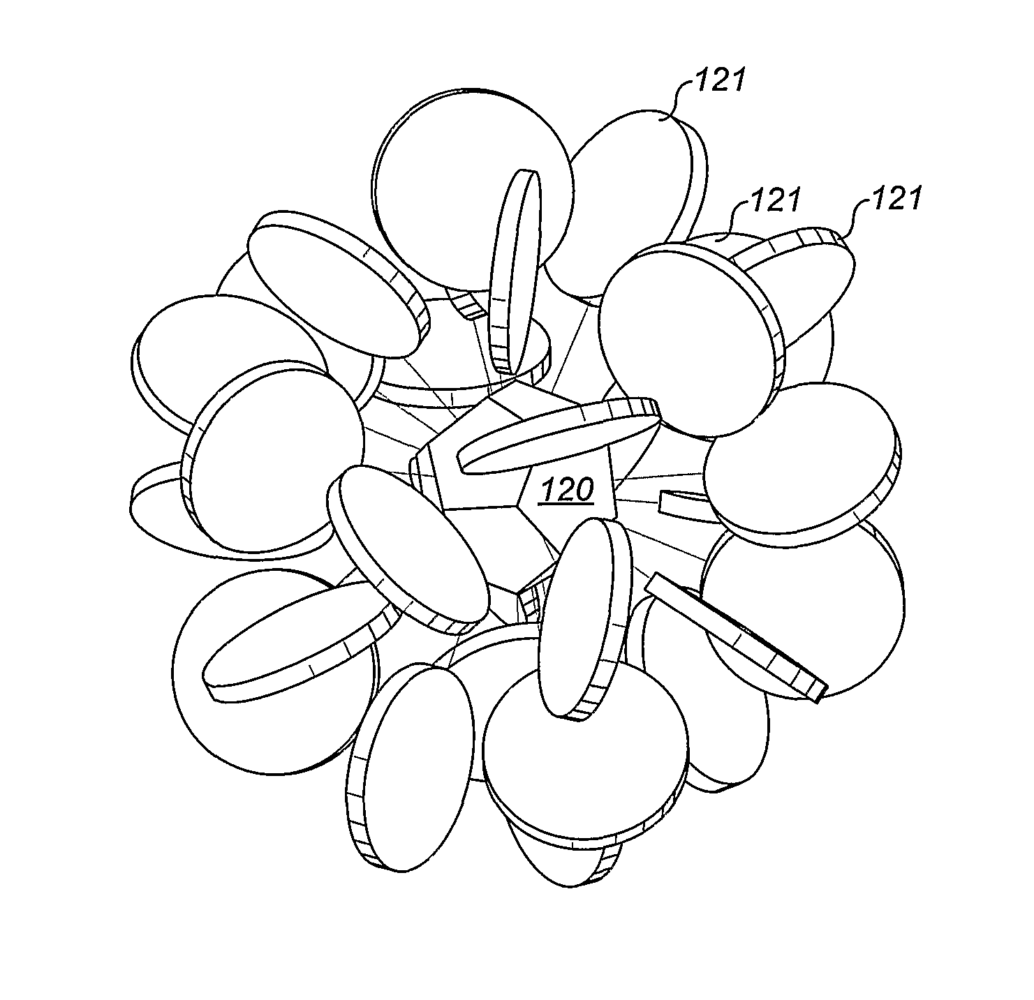
[0065]The first systematic description of a method to do this is described by Craven, P. G. and Gerzon, M. A. in British patent GB1512514 (“Coincident microphone simulation covering three dimensional space and yielding various directional outputs” and by Gerzon, M. A. in “The Design of Precisely Coincident Microphone Arrays for Stereo and Surround Sound”, Preprint L-20, 50th convention of the Audio Engineering Society (February 1975). These documents disclose the possibility of a sphere densely covered with microphones, or covered with a small number of strategically-placed microphone sensors. A suitable ...


PUM


Abstract

A sound capture device comprises a symmetric microphone array that includes non-radially-oriented directional sensors (101). The device typically derives a spherical harmonic representation of the incident sound field, and affords higher signal-to-noise ratios and better directional fidelity than prior arrays, across a wide range of audio frequencies.

Description

[0001]This application is a U.S. National Stage filing under 35 U.S.C. §371 and 35 U.S. §119, based on and claiming priority to PCT / GB2007 / 003782 for “MICROPHONE ARRAY” filed Oct. 5, 2007, claiming priority to GB Patent Application No. 0619825.3 filed Oct. 6, 2006.FIELD OF THE INVENTION[0002]The invention relates to the field of microphone arrays, and in particular the synthesis of high order directivities.BACKGROUND TO THE INVENTION[0003]An acoustic field has two physical characteristics that can be sensed: pressure and velocity. Pressure is a scalar quantity whereas velocity is a vector quantity. Conventional studio microphones sense one of these quantities or a linear combination of the two. An ‘omnidirectional’ microphone senses pressure, while a ‘figure-of-eight’ microphone senses velocity (or ‘pressure gradient’, which is closely related to velocity). Other types (subcardioid, cardioid, supercardioid and hypercardioid) sense a linear combination of pressure and velocity.[0004]...

Claims


Application Information

Patent Timeline
Patent Type & Authority Patents(United States)
IPC IPC(8): H04R25/00
CPCH04R5/027H04S3/00H04S2400/15H04S2420/11H04R1/406H04R2201/401
Inventor CRAVEN, PETER G.LAW, MALCOLMTRAVIS, CHRIS
Owner CRAVEN PETER G
Why Eureka
Try Eureka