
Fuel cell system with partial external reforming and direct internal reforming

a fuel cell and internal reforming technology, applied in the field of fuel cells, can solve the problem of low percentage of fuel that is internally reformed, and achieve the effect of simplifying the control means and simplifying the flow routing

Active Publication Date: 2013-04-02
MODINE MFG CO
View PDF11 Cites 2 Cited by
  • Summary
  • Abstract
  • Description
  • Claims
  • Application Information

AI Technical Summary

Benefits of technology

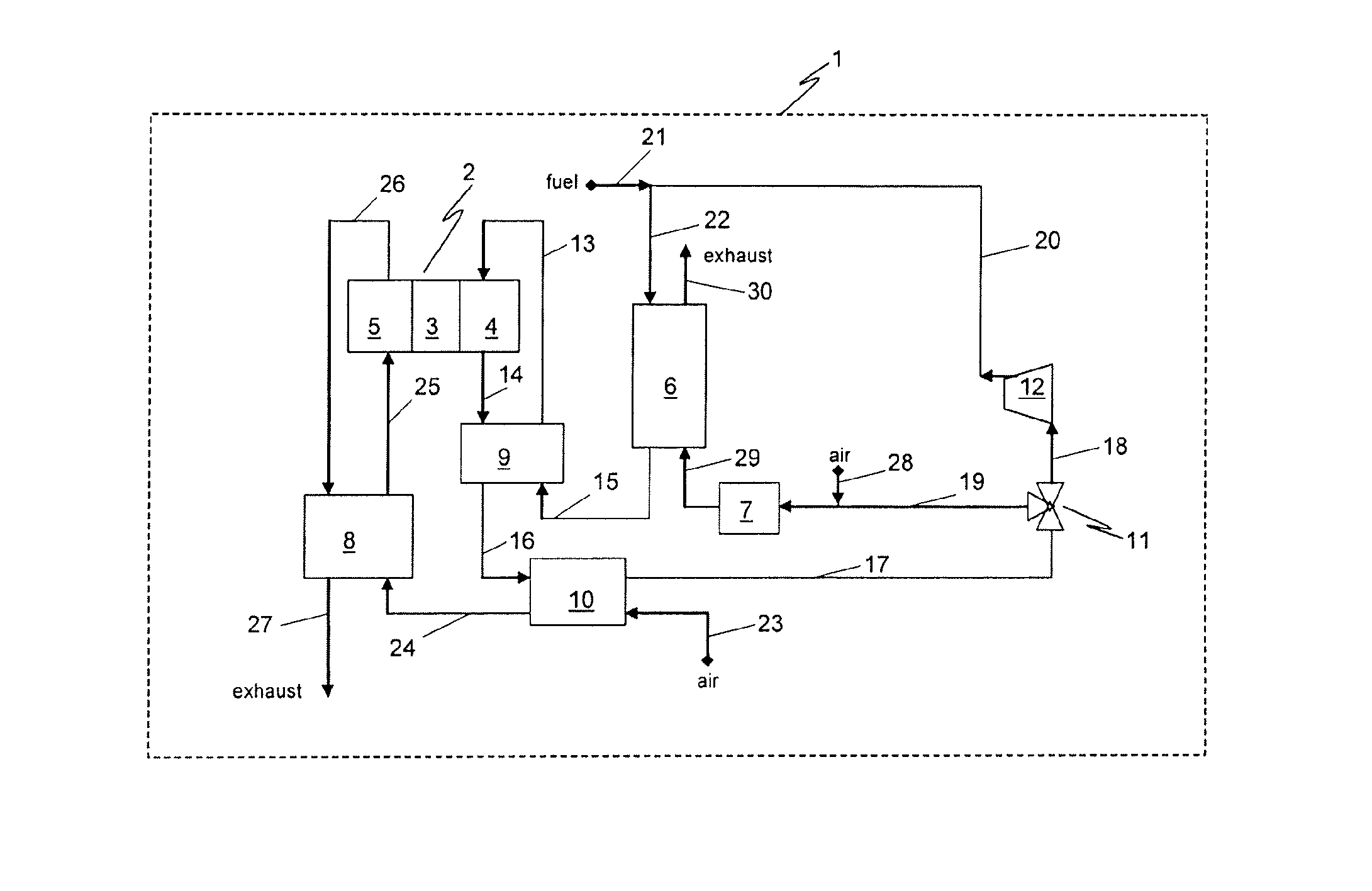
The present invention provides a fuel cell system that can have both partial external and direct internal reforming means, and the amount of direct internal reforming can be adjusted through a simplified control means and flow routing. The system can also rapidly start and stably operate at low power output levels. The system includes a plurality of solid oxide fuel cells, a heat exchanger / reformer, and an anode tailgas oxidizer (ATO). The cooled anode offgas is split into a first portion to be oxidized in the ATO and a second portion to be recycled back to the fuel cell anodes, and that portion of the fuel not reformed within the heat exchanger / reformer is direct internally reformed at the fuel cell anodes. The relative amount of direct internal reforming is controlled through varying the fuel utilization.

Problems solved by technology

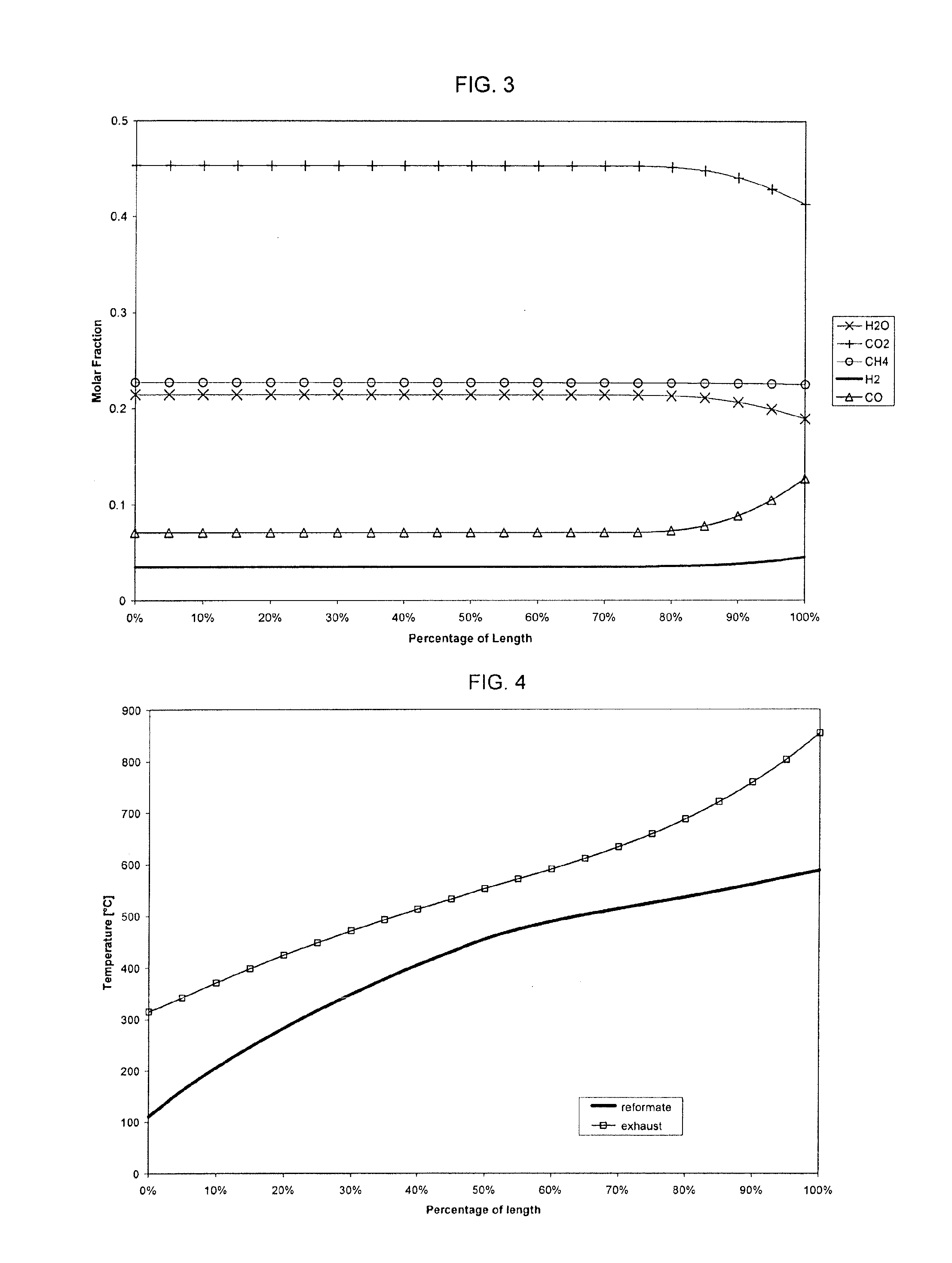
Therefore, at high levels of fuel utilization, the percentage of fuel that is internally reformed is high, and at low levels of fuel utilization, the percentage of fuel that is internally reformed is low.

Method used


Image

  • Fuel cell system with partial external reforming and direct internal reforming
  • Fuel cell system with partial external reforming and direct internal reforming
  • Fuel cell system with partial external reforming and direct internal reforming

Examples


Embodiment Construction

[0019]Before any embodiments of the invention are explained in detail, it is to be understood that the invention is not limited in its application to the details of construction and the arrangement of components set forth in the following description or illustrated in the following drawings. The invention is capable of other embodiments and of being practiced or of being carried out in various ways. Also, it is to be understood that the phraseology and terminology used herein is for the purpose of description and should not be regarded as limiting. The use of “including,”“comprising,” or “having” and variations thereof herein is meant to encompass the items listed thereafter and equivalents thereof as well as additional items. Unless specified or limited otherwise, the terms “mounted,”“connected,”“supported,” and “coupled” and variations thereof are used broadly and encompass both direct and indirect mountings, connections, supports, and couplings. Further, “connected” and “coupled”...


PUM

PropertyMeasurementUnit
voltageaaaaaaaaaa
temperatureaaaaaaaaaa

Abstract

A fuel cell system includes a plurality of solid oxide fuel cells arranged in a fuel cell stack, an integrated heat exchanger / reformer operable to partially reform an anode feed prior to entry into the fuel cell stack, an anode tailgas oxidizer, and an offgas flow path extending away from an anode side of the fuel cell stack and having a first branch to selectively combine offgas from the anode side of the fuel cell stack with fuel from a fuel source to comprise the anode feed to the fuel cell stack and a second branch to supply offgas from the anode side of the fuel cell stack to the anode tailgas oxidizer. The integrated heat exchanger / reformer transfers heat from the oxidized offgas from the anode tailgas oxidizer to the anode feed before the anode feed enters the anode side of the fuel cell stack. The offgas from the anode tailgas oxidizer provides the sole heat source for the anode feed traveling through the integrated heat exchanger / reformer.

Description

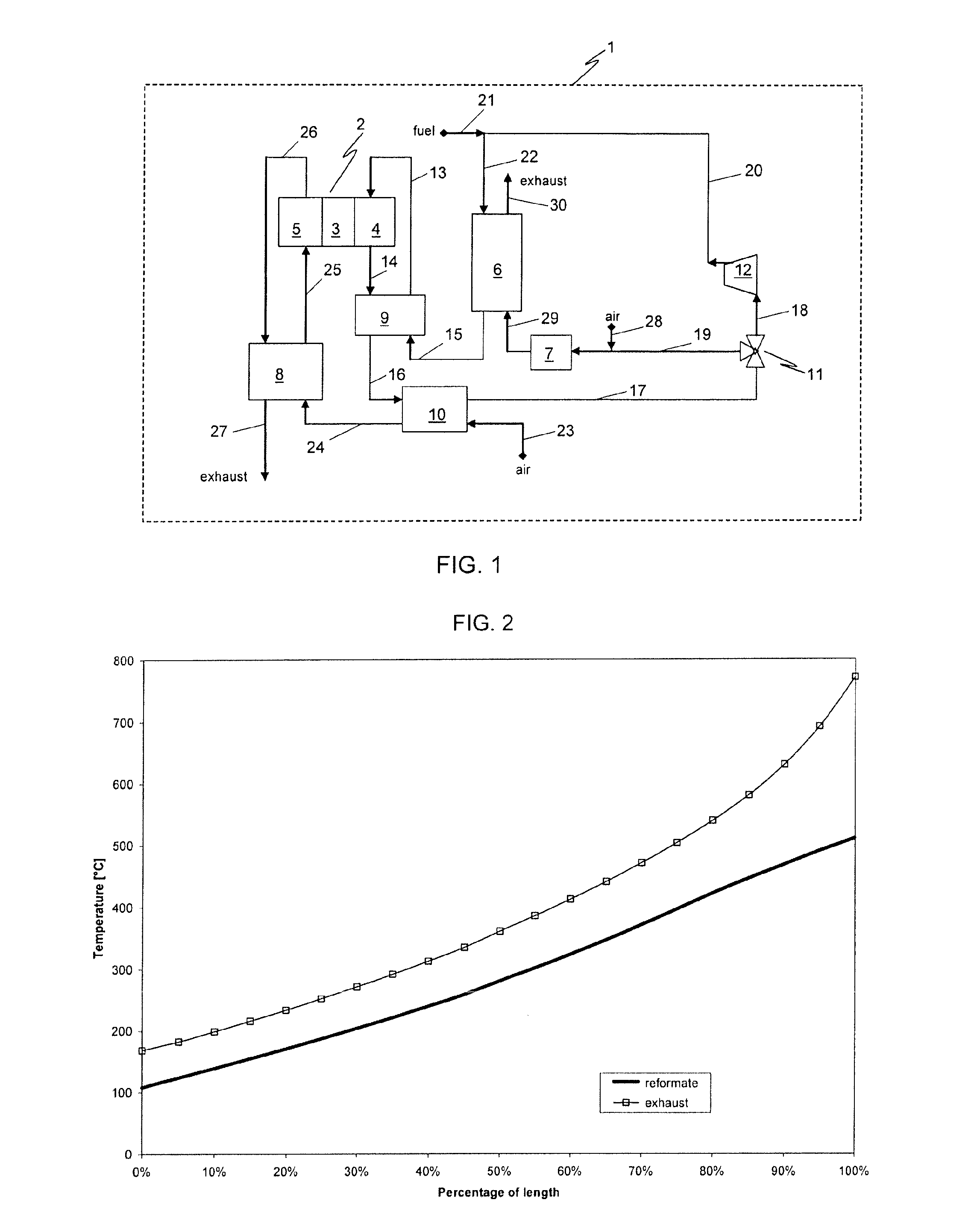
CROSS-REFERENCE TO RELATED APPLICATIONS[0001]This patent application is a national stage filing under 35 U.S.C. 371 of International Application No. PCT / US2008 / 060557, filed 17 Apr. 2008, and claims priority to U.S. Provisional Patent Application No. 60 / 923,885, filed 17 Apr. 2007, the entire contents of which are incorporated herein by reference.FIELD OF THE INVENTION[0002]The present invention relates to fuel cells, and in particular, to solid oxide fuel cells.SUMMARY OF THE INVENTION[0003]The fuel cell system of the present invention can have both partial external reforming and direct internal reforming means and the amount of direct internal reforming can be adjusted through a simplified control means and simplified flow routing.[0004]The present invention can also or alternatively provide a fuel cell system capable of operation at high thermal efficiency levels.[0005]The present invention can also or alternatively provide a process for rapidly starting a fuel cell system having...

Claims


Application Information

Patent Timeline
Patent Type & Authority Patents(United States)
IPC IPC(8): H01M8/00
CPCH01M8/0618H01M8/0637H01M8/0606H01M8/2425H01M2008/1293Y02E60/50Y02E60/525H01M8/04225H01M8/04302
Inventor VALENSA, JEROEN
Owner MODINE MFG CO
Learn More