Microwave coagulation applicator and system

a technology of micro-wave coagulation and applicator, which is applied in the field of microwave coagulation applicator and system, to achieve the effects of reducing microwave heating, increasing tissue heating, and reducing heating

Active Publication Date: 2013-04-09
VARIAN MEDICAL SYSTEMS
View PDF92 Cites 41 Cited by
  • Summary
  • Abstract
  • Description
  • Claims
  • Application Information

AI Technical Summary

Benefits of technology

[0011]In one embodiment of the present invention, a microwave applicator for heat treatment of diseased tissue within a living body includes a handle by which the applicator can be held and manipulated for insertion into the living body. An elongate applicator body having an insertion end for insertion into a tissue region of the living body extends from the handle which usually forms the attachment end of the applicator. An antenna is disposed toward the insertion end of the applicator body. Microwave energy is conducted from the handle to the antenna via a microwave energy transmission line in the form of a coaxial cable disposed within the applicator body. The coaxial cable includes an inner conductor and an outer conductor separated by a dielectric material therebetween. An outer conductive sleeve extends from the handle to an insertion end of the outer conductive sleeve which is separated from the conductive tip by a gap, usually filled with a dielectric material. The outside diameters of the insertion tip, the outer conductive sleeve, and the dielectric material filling the gap therebetween are all about equal so as to form a substantially smooth continuous elongate applicator body, for insertion into the living body. The elongate applicator body, or at least the portion thereof to be inserted into a living body, may be coated with a stick resistant dielectric material such as Teflon. This can at least partially reduce the sticking of coagulation tissue to the applicator outer surface, particularly in the areas of tissue coagulation and ablation, to facilitate removal of the applicator after treatment.
[0015]The temperature sensor used in the applicator may be a thermistor. The resistance of a thermistor varies with the temperature of the thermistor. The temperature measured by the thermistor is obtained by an external circuit that measures the temperature by causing a constant dc current to flow through the thermistor. The resistance of the thermistor then produces a dc voltage that is indicative of the temperature of the thermistor. The temperature sensor in the handle, or a temperature sensor positioned along the applicator, may be coupled to the flexible coaxial cable extending from the microwave generator through a coupling network, such as a resistive and capacitive coupling network. The resistive and capacitive coupling network allows a dc current from the coaxial cable conductors to flow to and from the thermistor while isolating the thermistor from the microwave power signals, and allows the microwave power signals to flow to the antenna while isolating the antenna from the dc current. Similarly, a coupling network can be used at the opposite end of the flexible coaxial cable, such as in power splitting and multiplexing circuitry, to separate the dc temperature signals from the flexible coaxial cable conductors and direct them to temperature sensing circuitry in a system controller while isolating the temperature sensing circuitry from the microwave power signals, and passing the microwave power signals from the system microwave generator while isolating the system microwave generator from the dc temperature signals. The use of a computer in the system controller to sense forward power, reflected power, measure the thermistor temperature, and possibly monitor other variables such as monitoring tissue temperature by one or more independently inserted temperature sensors, provides control and feedback for the applied microwave power and the proper safety and operation of the microwave coagulation or ablation procedure.
[0017]The use of phased arrays can also reduce microwave heating along the shafts of the applicators due to cross coupling of the energy between the antennas that are driven in phase and separated by a distance that provides for partial power cancellation along the outer portion of the inserted applicators and an increase in tissue heating between these inserted applicators. This partial power cancellation is accomplished when the distance between approximately parallel inserted antennas is approximately a half of a wavelength so that the cross coupled energy is somewhat out of phase with that on an antenna due to its own radiated energy. For a frequency of 915 MHz, for example, the wavelength in typical high water content tissues such as muscle and tumors is approximately 4.3 to 4.7 cm. This means that for an insertion separation of 2.1 to 2.4 cm the separation is about right for this 180 degree relationship. There is also cross coupled phase cancellation for significant phase differences other than 180 degrees, for example, a 135 or 225 degree phase difference will still provide partial phase cancellation from the cross coupling of the microwave coupled fields to partially cancel microwave energy along the outer portion of the inserted applicators. This would be consistent with an applicator spacing of between about 1.6 to 3.0 cm for the 915 MHz example. This partial cancellation of microwave power around the inserted shafts results in reduced heating along the inserted shafts during active microwave tissue heating. This also reduces the local power fields locally around the radiating antennas and the outer shafts to reduce tissue sticking to the antennas and shafts.
[0018]The control of the heating may further include the systematic use of applicators in phased arrays with optimization computational guidance in the form of pretreatment planning to provide an ideal insertion pattern and power and phase application to the array of applicators to produce and control improved uniformity of power deposition, temperatures, and / or coagulation of tissue throughout the tumor volume, and particularly at the tumor margins. The treatment is thereby optimized and controlled by the aid of a numerical calculation of either the planned insertion pattern and number of antennas or the actual pattern achieved as indicated by various non-invasive imaging processes such as computer tomography (CT), ultrasound, or magnetic resonance imaging (MRI). It also may be feasible to use such planning information to adjust power amplitude and phase of each of the inserted applicators as directed by a computer-controlled system using the predicted power patterns from the computer numerical model.
[0019]In a phased array embodiment of the invention, a single microwave generator is used to provide the microwave power for all applicators. The generator will usually operate at 915 MHz, which is an emission frequency commonly licensed for medical applications. This single generator is connected to a passive, non-switching, microwave impedance matched power splitter (divider) which is used to direct power simultaneously to multiple ports that are connected to one or more microwave dipole antennas such as described for the above described applicators. This arrangement provides approximately equal power simultaneously to each of the output connection ports. This arrangement also provides equal phase output of the microwave energy at each of the output ports. Thus, when multiple antennas are connected to the ports of the power splitter, they have equal power and equal relative phase and are thus correctly called a phased array of antennas. The cables going to the radiating points on each antenna are maintained at the same electrical length so that the radiated energy from the antennas are phase synchronous and phase coherent. Phase synchronous meaning that there is a fixed phase relationship between the radiation phase of all antennas and phase coherent meaning that the relative radiated phase from each antenna is approximately the same. The use of phased arrays as described increases the heating in the spaces between the antennas by providing improved uniformity of the coagulation of the targeted tissue providing more power absorption than when using channel switching and other non-phase synchronous and non-simultaneous channel operation methods.
[0023]The design of a narrow separation gap between the conductive applicator insertion tip and the insertion end of the conductive outer sleeve provides a zone of high microwave intensity at the gap which can be used to coagulate tissues along the insertion track if the microwave power is applied as the microwave antenna is withdrawn from the treated tissue. This provides coagulation of tissue and blood vessels that may be along the insertion track as well as any disease tissue that may be along the track as the applicator is removed from the tissue. By providing regularly spaced depth markings on the elongate applicator and withdrawing the applicator from the living body in coordination with regular cadence sounds, a substantially constant rate of removal of the applicator from a living body can be achieved for effective track ablation.

Problems solved by technology

Because cooling is not normally needed in the tissue to be heated during coagulation and ablation treatments, cooling is not provided in the area of the radiating antenna of the applicator where the heating of tissue is desired.

Method used


Image

  • Microwave coagulation applicator and system
  • Microwave coagulation applicator and system
  • Microwave coagulation applicator and system

Examples


Embodiment Construction

[0034]Reference will now be made to the exemplary embodiments illustrated in the drawings, and specific language will be used herein to describe the same. It will nevertheless be understood that no limitation of the scope of the invention is thereby intended. Alterations and further modifications of the inventive features illustrated herein, and additional applications of the principles of the inventions as illustrated herein, which would occur to one skilled in the relevant art and having possession of this disclosure, are to be considered within the scope of the invention.

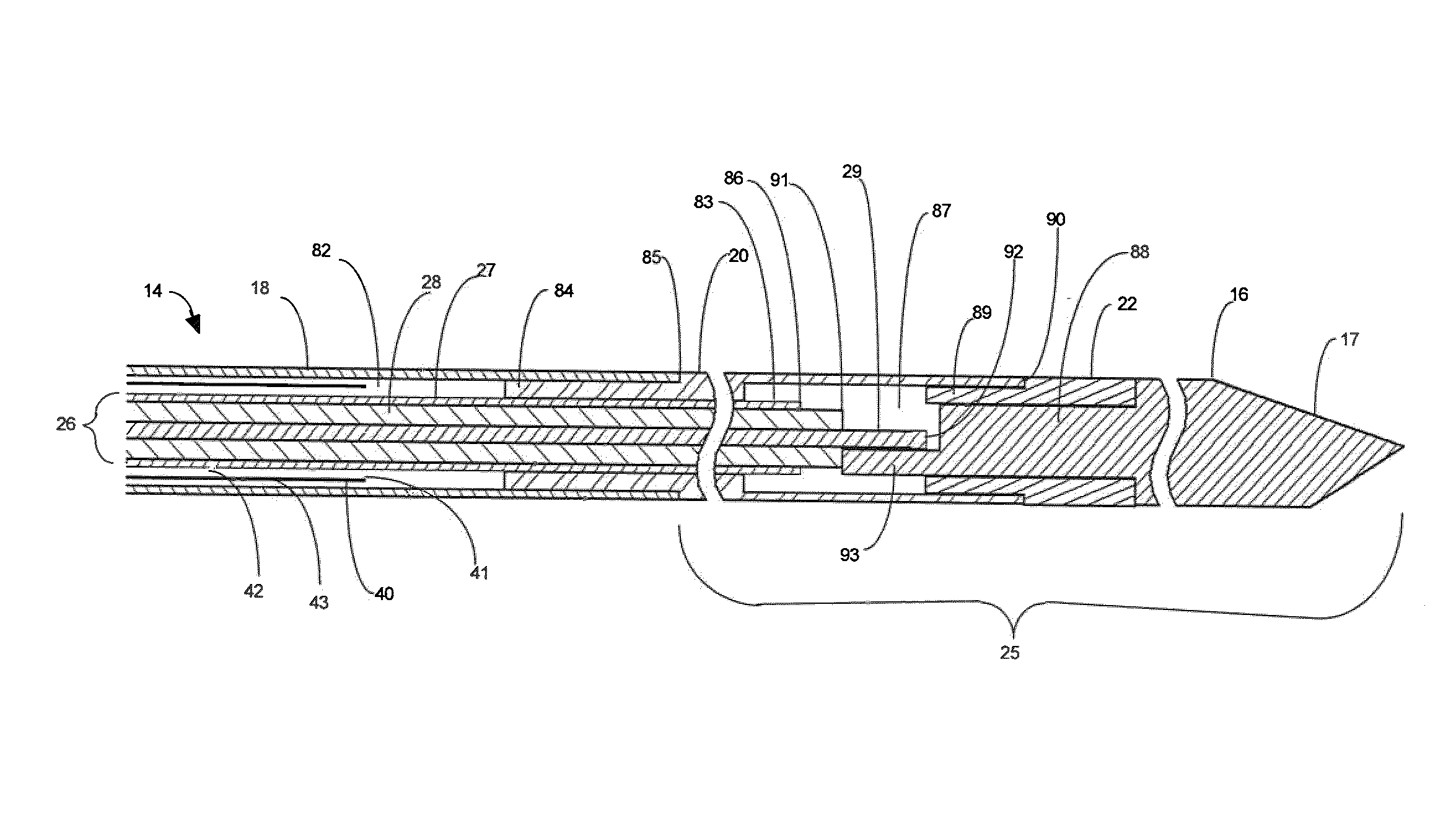
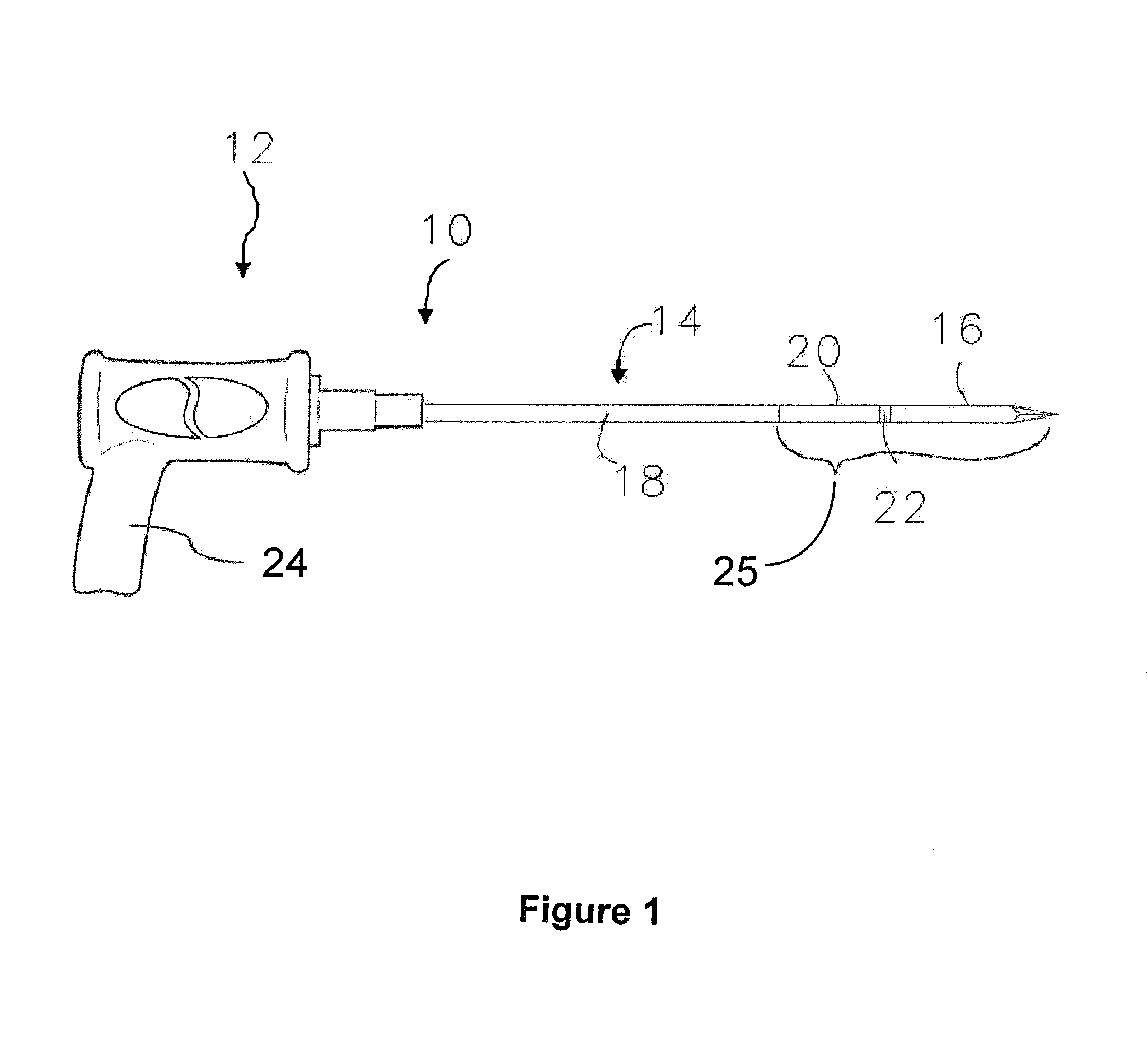
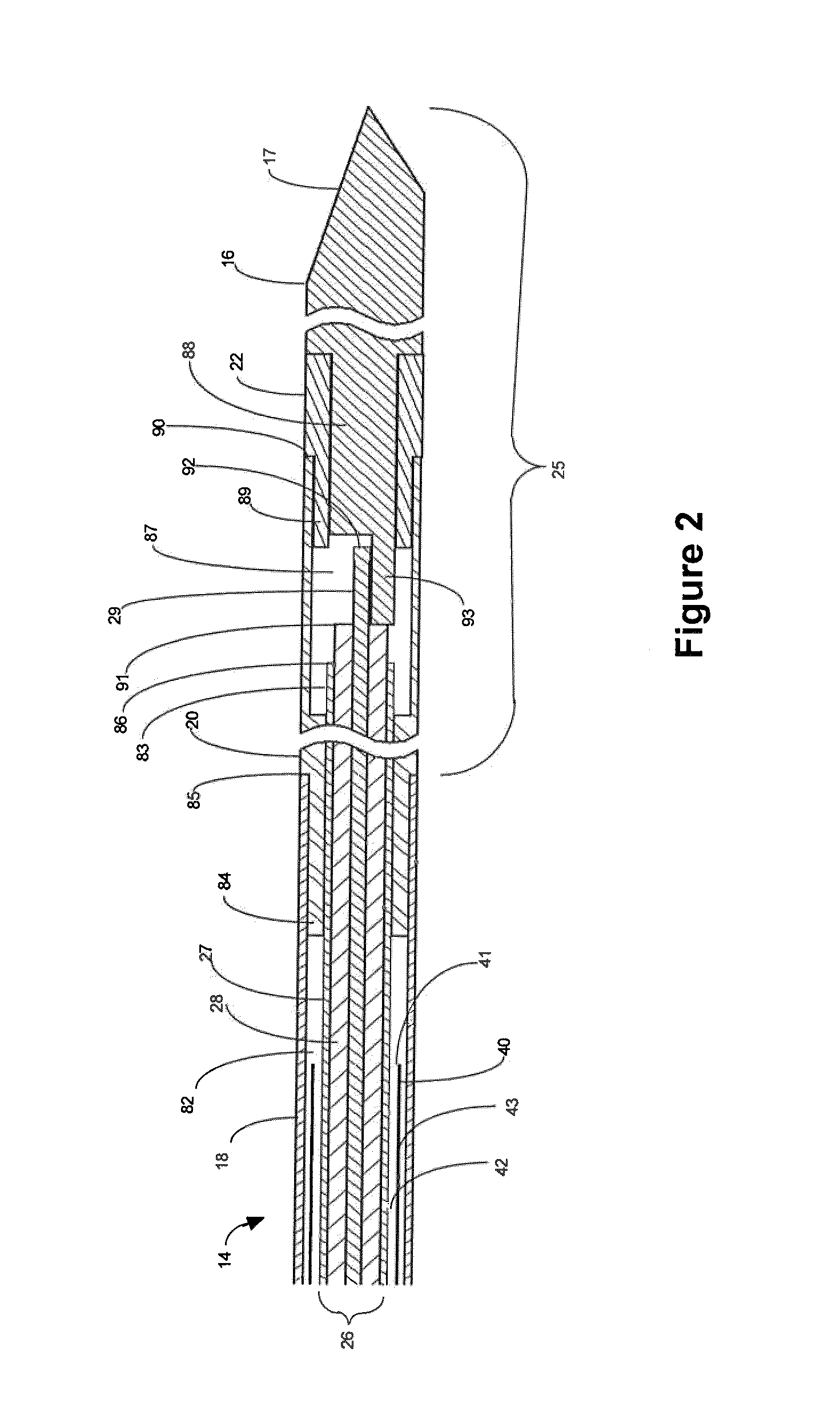
[0035]One embodiment of a microwave applicator of the invention for microwave coagulation and ablation treatment of diseased tissue within living body tissue is illustrated in FIG. 1. The applicator, referred to generally as 10, includes a handle 12 from which a substantially rigid elongate applicator body 14 extends with an insertion tip 16 forming the insertion end portion of the applicator for insertion into a...


PUM


Abstract

A microwave applicator for insertion into living body tissue for use in microwave coagulation and ablation treatments includes a microwave transmission line extending between an attachment end of the applicator and an antenna toward an insertion end of the applicator with an outer conductive sleeve forming an enclosed cooling fluid space around the transmission line. Circulation of cooling fluid is guided in the cooling fluid space by a guide sleeve. A temperature sensor senses the approximate temperature of cooling fluid to indicate cooling fluid is circulating. A multiplexing and power splitting circuit provides outputs tuned for one or for more than one applicator to be attached and detects the number of applicators and correct connection. A cadence sound generator can be used in conjunction with depth markings on the applicator to provide substantially constant withdrawal of the applicator from the treated tissue after treatment to provide track ablation.

Description

BACKGROUND OF THE INVENTION[0001]1. Field[0002]This invention relates to electromagnetic radiation (EMR) therapy and more particularly to applicators and systems for applying electromagnetic energy to a treatment site in a living body to heat tissue needing treatment at the treatment site. The invention is useful particularly for treatments in the nature of microwave coagulation or ablation.[0003]2. State of the Art[0004]The use of electromagnetic (EM) energy to heat tissue for the treatment of disease is known. In using microwave energy for tissue heating, an applicator having a microwave radiating antenna is positioned with respect to the tissue to be treated (heated) so that microwave energy radiated from the antenna penetrates and heats the tissue. Many microwave applicators are known in the art. Death, or necrosis, of living tissue cells occurs at temperatures elevated above a normal cell temperature for a sufficient period of time. The sufficient period of time is generally de...

Claims


Application Information

Patent Timeline
Patent Type & Authority Patents(United States)
IPC IPC(8): A61B18/14
CPCA61B18/1815A61B2017/00022A61B2018/00023A61B2018/1869A61B2018/1892
Inventor TURNER, PAUL F.YOUD, THOMAS L.
Owner VARIAN MEDICAL SYSTEMS
Why Eureka
Try Eureka