
Boundary buffers to model register incompatibility during pre-retiming optimization

a buffer and register technology, applied in the field of electronic design automation, can solve the problems of inability to account for the limitations of register movement and merging, the retiming may dramatically alter the relative timing criticality, and the approach is experimental and not widespread in the industry

Active Publication Date: 2013-04-16
CADENCE DESIGN SYST INC
View PDF5 Cites 18 Cited by
  • Summary
  • Abstract
  • Description
  • Claims
  • Application Information

AI Technical Summary

Benefits of technology

The patent text describes a method for capturing the ability of a circuit to change the timing of its elements to balance delays and improve performance. This method can be used with existing techniques and can be transparent to most optimizations. It includes the use of timing elements that can disallow the use of certain values in the circuit and can also include elements that adjust the timing model of the circuit. Overall, this method allows for more flexibility and improved performance of the circuit.

Problems solved by technology

Because the movement of registers redistributes timing slack in the design, retiming may dramatically alter the relative timing criticality at any given point in the design.
While it is possible to formulate fully sequential timing aware optimization algorithms that as such are inherently retiming aware, such approaches are experimental and not widespread in industry at this time.
A problem with both of these techniques, however, is that they are unable to account for limitations on register movement and merging due to incompatible clock, reset, voltage, or enable signals, or other features, merely by way of example.
Thus, the existing approaches to modeling incompatible registers generally limit the timing adjustment at the original register location based upon the minimum or maximum compatible movement along any fan-in / fan-out path from the register.
With the over-conservative limitation of register compatibility, the less-constrained paths may appear overly timing-critical.
The result may be a circuit with timing violations or with sub-optimal timing; it is possible for the timing of the final result to be worse than that of the original.
Intermediate bounds are also possible but simultaneously suffer from both of the above limitations.

Method used


Image

  • Boundary buffers to model register incompatibility during pre-retiming optimization
  • Boundary buffers to model register incompatibility during pre-retiming optimization
  • Boundary buffers to model register incompatibility during pre-retiming optimization

Examples


Embodiment Construction

[0042]The ensuing description provides preferred exemplary embodiment(s) only, and is not intended to limit the scope, applicability or configuration of the disclosure. Rather, the ensuing description of the preferred exemplary embodiment(s) will provide those skilled in the art with an enabling description for implementing a preferred exemplary embodiment. It being understood that various changes may be made in the function and arrangement of elements without departing from the spirit and scope as set forth in the appended claims.

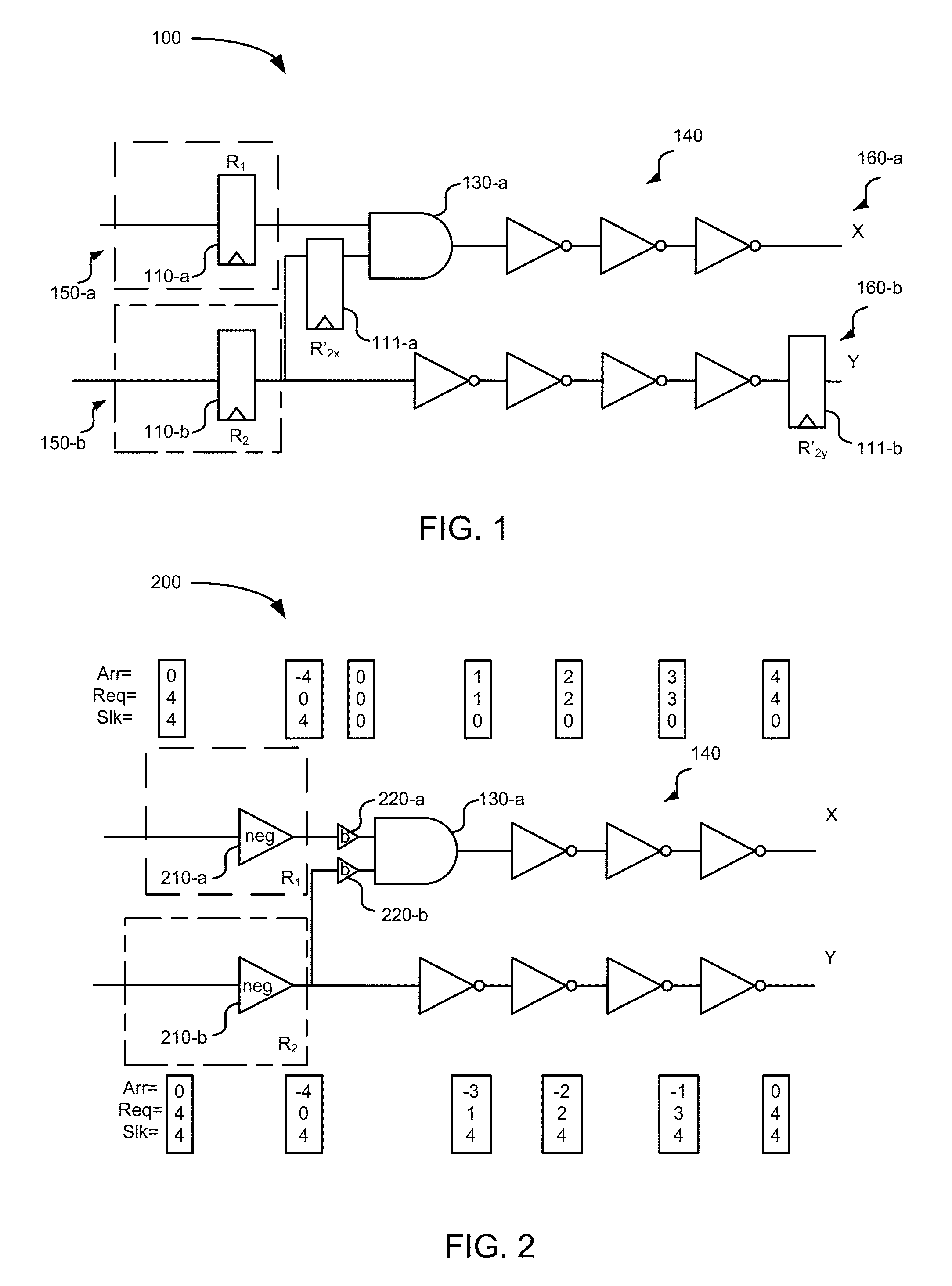
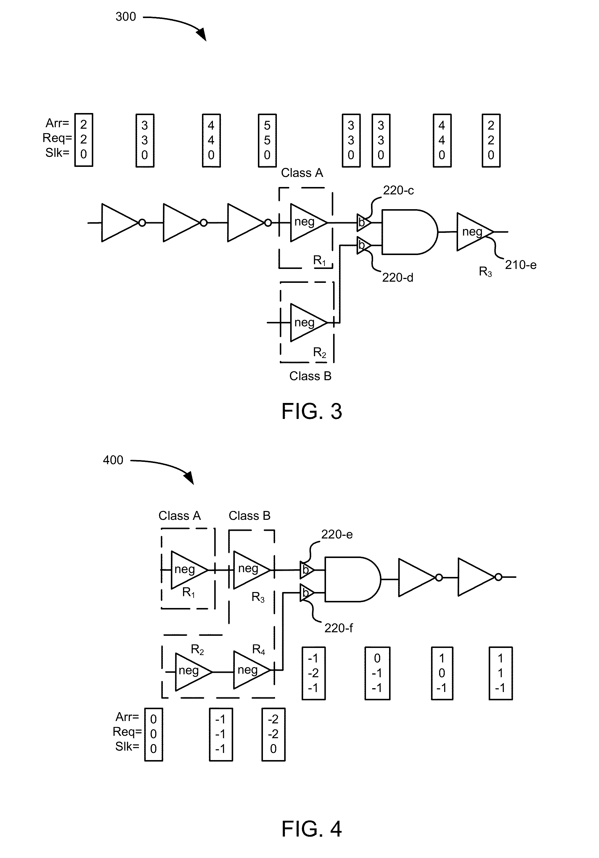
[0043]Methods, systems, and machine-readable storage medium are disclosed to model the timing consequences of memory element class incompatibility during retiming (due to different clock, reset, voltage, or enable signals, merely by way of example) in the synthesis steps that may occur prior to retiming. Embodiments disclose timing elements that may be referred to as a retiming boundary buffers. The timing elements may include properties such that its dela...


PUM


Abstract

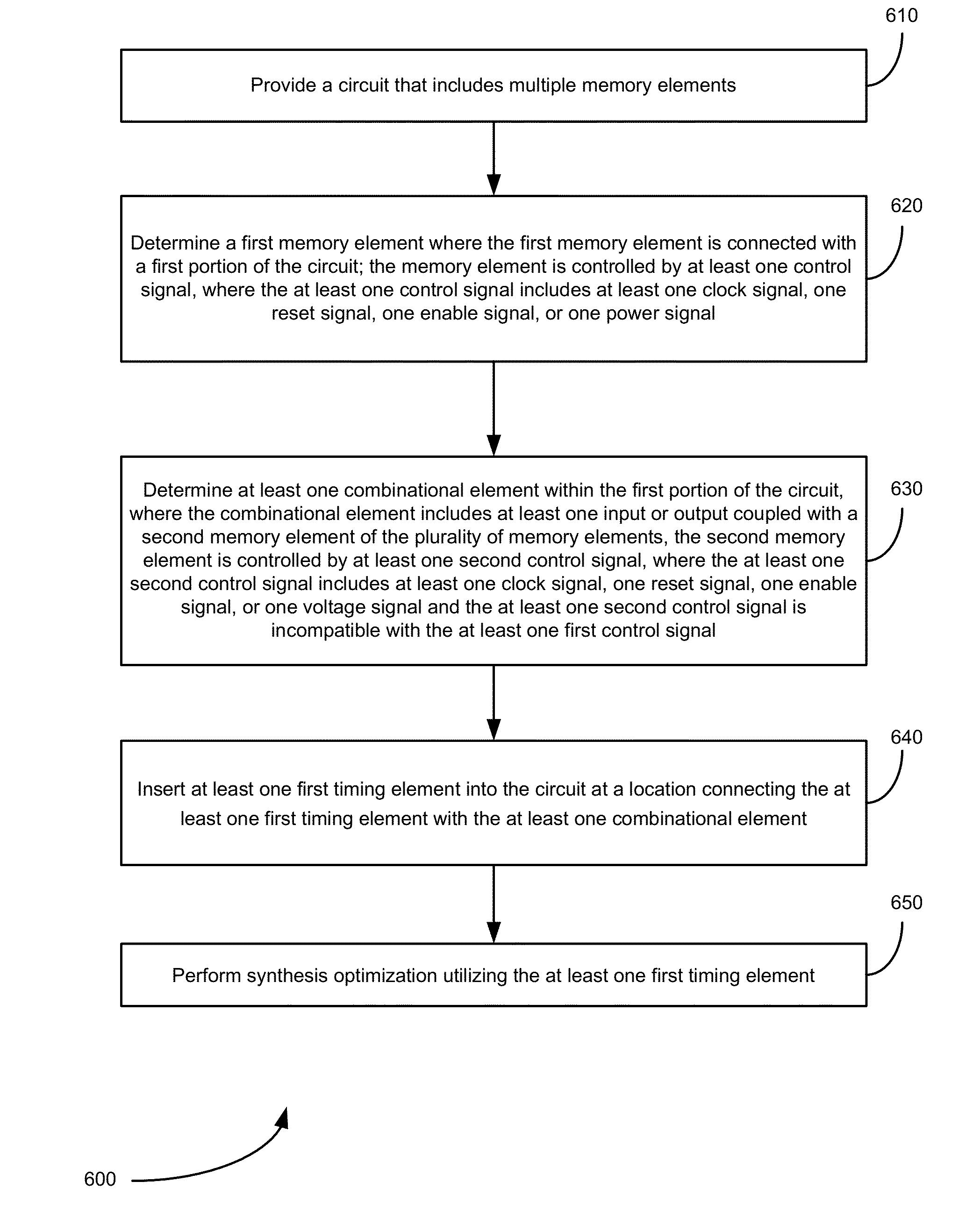
Methods, systems, and machine-readable storage medium for logic synthesis that adjust a timing model of a circuit are provided. A first memory element from multiple memory elements of the circuit may be determined, where the first memory element is connected with a first portion of the circuit and is controlled by at least one first control signal. A combinational element within the first portion of the circuit may be determined. The combinational element may include at least one input or output coupled with a second memory element. The second memory element may be controlled by at least one second control signal. The second control signal may be incompatible with the first control signal. A first timing element may be inserted into the circuit at a location connecting the first timing element with the combinational element. A synthesis optimization may be performed utilizing the at least one first timing element.

Description

BACKGROUND[0001]This disclosure relates in general to electronic design automation (EDA) and, more specifically, logic synthesis of a circuit involving retiming.[0002]Retiming is a technique of logic synthesis optimization that relocates registers such as flip-flops, or memory elements more generally, in a circuit in a manner that preserves the output functionality. Retiming may be applied to achieve different purposes, such as to minimize or to meet a constraint on a worst case combinational delay and / or to minimize the number of registers. Because the movement of registers redistributes timing slack in the design, retiming may dramatically alter the relative timing criticality at any given point in the design. Paths with significant slack may become critical after retiming, and paths that are initially critical may be easily fixed.[0003]It may therefore be beneficial to provide an early estimate of the post-retiming / sequential timing model to the synthesis operations that occur be...

Claims


Application Information

Patent Timeline
Patent Type & Authority Patents(United States)
IPC IPC(8): G06F17/50G06F9/455
CPCG06F17/505G06F2217/84G06F30/327G06F2119/12
Inventor HURST, AARON
Owner CADENCE DESIGN SYST INC
Learn More