Method of forming composite powder metal gear

a technology of composite powder metal and gear, which is applied in the direction of transportation and packaging, solid-state diffusion coating, other domestic articles, etc., can solve the problems that the mechanical properties of carburized gear do not necessarily achieve the desired effect, and achieve the effect of greater tooth wear resistance, greater impact resistance, and greater tooth wear resistance on the teeth

Inactive Publication Date: 2013-04-23
SKN SINTER METALS LLC (US)
View PDF18 Cites 5 Cited by
  • Summary
  • Abstract
  • Description
  • Claims
  • Application Information

AI Technical Summary

Benefits of technology

The patent describes a special gear made from a special powder metal material that has been forged to have a unique design on its surface and core that improves its ability to resist tooth wear (when teeth are worn down) and impact (when the gear is hit hard). This design uses a special technique called a "variable boundary profile" that is formed between two sections of the gear, which results in better protection against these damaging forces.

Problems solved by technology

However, a case carburized gear does not necessarily achieve the desired mechanical properties such as enhanced tooth wear and fatigue strength while providing beneficial performance characteristics in the body of the gear that could beneficially result if the part was made from composite materials.

Method used


Image

  • Method of forming composite powder metal gear
  • Method of forming composite powder metal gear
  • Method of forming composite powder metal gear

Examples


Embodiment Construction

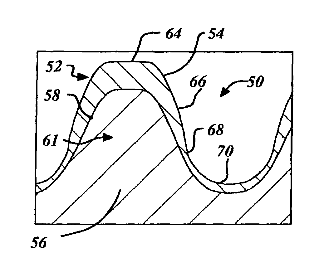
[0016]In all figures, the same reference numerals are used to identify like parts in the various views. Thus, simultaneous reference to the various figures is appropriate. In some instances, for clarity, equivalent parts in different figures may have different reference numbers.

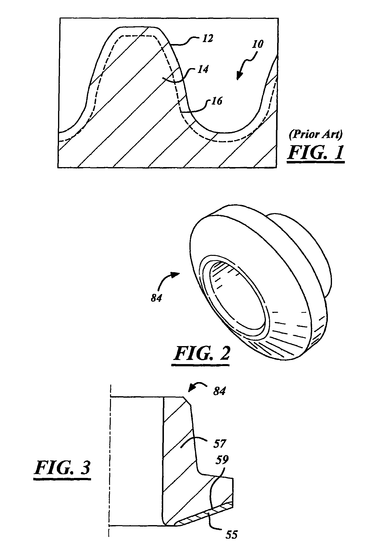
[0017]FIG. 2 shows an isometric view of a composite preform 84 made after compacting and sintering required to obtain the inventive product after forging in accordance with an embodiment of the invention.

[0018]FIG. 3 shows a partial cross-sectional view of the composite preform 84 of FIG. 2 having a composite material. The preform 84 includes a first powder metal material 55 and a second powder metal material 57 separated by initial material boundary 59. The initial material boundary 59 is representative of the boundary between at least two materials obtained after a compacting process of strategically filled or placed powder metals into a compaction die. While the initial material boundary 59 is shown as a p...


PUM

PropertyMeasurementUnit
hardnessaaaaaaaaaa
shear strengthaaaaaaaaaa
brinnelling resistanceaaaaaaaaaa

Abstract

A forged composite gear and a method of making a forged composite powder metal gear. The forged composite gear includes a plurality of teeth extending from a core, a first section having a first powder metal material, a second section having a second powder metal material and a variable boundary profile. The variable boundary profile is formed between the first section and the second section, whereby said variable boundary profile exhibits greater tooth wear resistance on the teeth and greater impact resistance in the core.

Description

CROSS-REFERENCE TO RELATED APPLICATIONS[0001]This application is a divisional patent application of U.S. non-provisional patent application Ser. No. 11 / 277,374 filed Mar. 24, 2006 now abandoned, which is hereby incorporated by reference as if set forth in its entirety herein.TECHNICAL FIELD[0002]The invention relates to a forged powder metal part and more particularly to a composite powder metal variable boundary part, including a method of manufacture thereof.BACKGROUND OF THE INVENTION[0003]There is continuing demand for manufacturing processes that may lessen the cost, time or steps in producing a part. More often than not, the benefits resultantly associated with improving the manufacturing process are necessitated in the first instance by customer requirements to develop and improve products to have superior dimensional, mechanical and / or performance properties. For instance a typical differential side gear may have any or all of the following performance requirements such as: ...

Claims


Application Information

Patent Timeline
Patent Type & Authority Patents(United States)
IPC IPC(8): B21D53/28B21K1/30
CPCB21K1/30F16H55/06F16H55/17Y10T29/49474Y10T29/49462Y10T29/49478Y10T29/49467Y10T74/19958
Inventor GEIMAN, TIMOTHY E.
Owner SKN SINTER METALS LLC (US)
Why Eureka
Try Eureka