
Device and method for transmitting light signals

a technology of light signals and devices, applied in the field of devices and methods for transmitting light signals, can solve the problems of increasing the overall dimensions and cost of the microfluidic system, rough surfaces, and inability to transmit light signals, so as to reduce the effect of attenuation of light signals

Inactive Publication Date: 2013-04-23
NAT CHIAO TUNG UNIV
View PDF7 Cites 4 Cited by
  • Summary
  • Abstract
  • Description
  • Claims
  • Application Information

AI Technical Summary

Benefits of technology

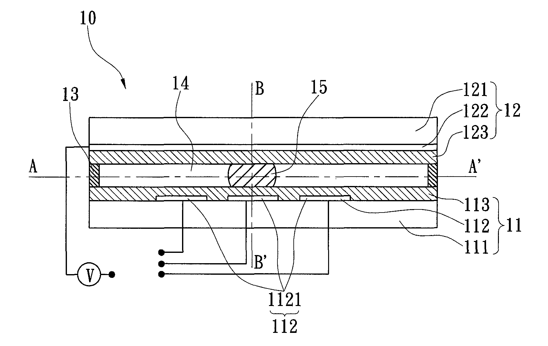
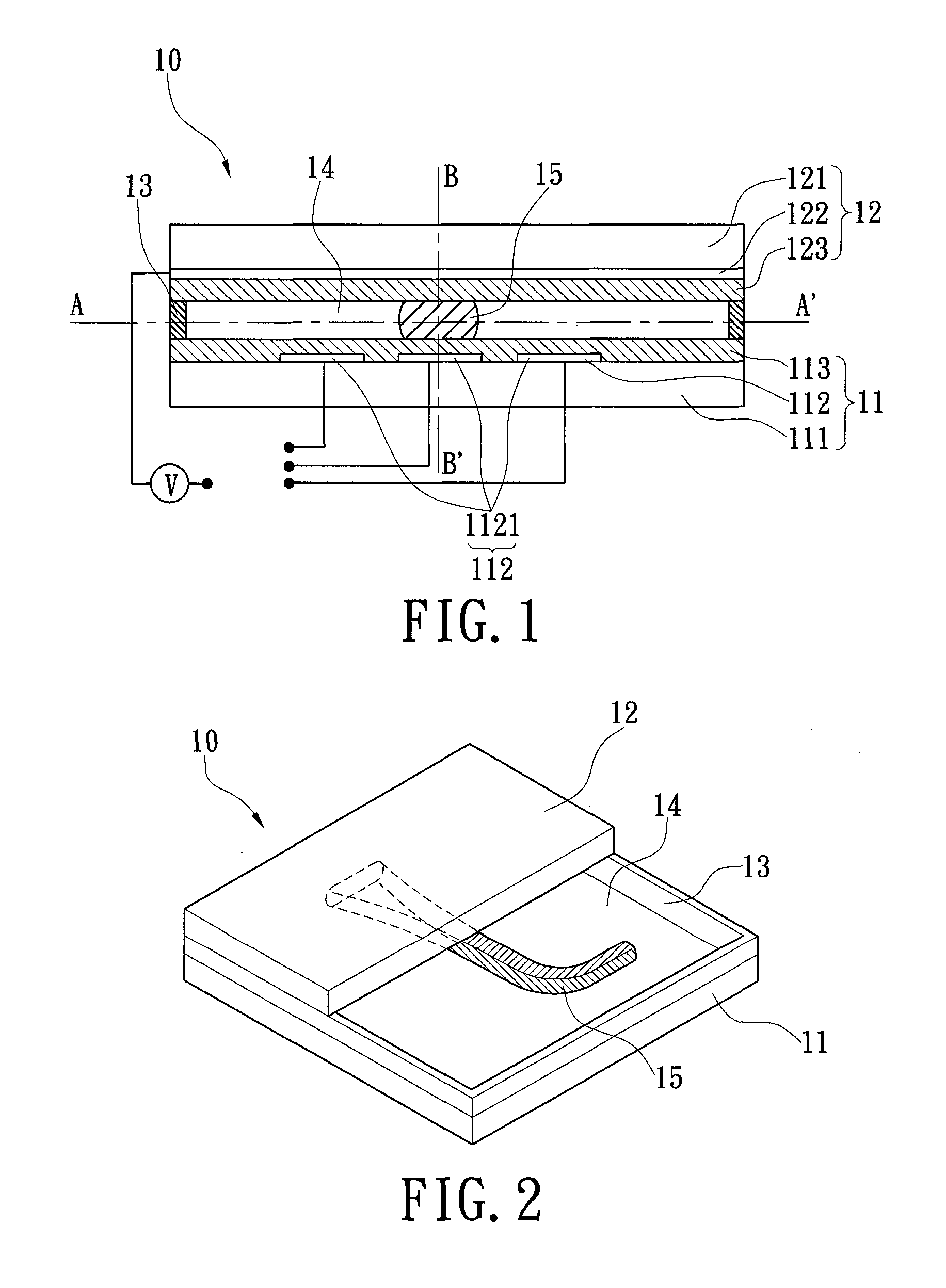
The present invention provides a device and method for transmitting light signals using a device that eliminates the use of solid walls of microchannels. This results in improved directionality and reduced light signal attenuation. The device employs a shape-changed core fluid surrounded by a cladding fluid to form an optical waveguide, allowing light signals to be transmitted without scattering. Additionally, the interface between the core and cladding fluids is smoother, leading to reduced intensity of the light ray. The shape-changed core fluid can also be easily deformed by altering the electric field, making the liquid optical waveguide electrically programmable.

Problems solved by technology

The microchannel is made of solid materials, so its surfaces are inevitably rough and irregular after manufacturing.
Furthermore, the pump of the microfluidic system is another shortcoming of the microfluidic system, because it increases the overall dimensions and cost of the microfluidic system.

Method used


Image

  • Device and method for transmitting light signals
  • Device and method for transmitting light signals
  • Device and method for transmitting light signals

Examples


second embodiment

[0052]Please refer to FIG. 9, the device 10 is disclosed. The first patterned electrode layer 112 comprises a spiral shaped electrode 1121; the core fluid 15 would change its shape to a spiral one to fit the electrode 1121. Please refer to FIG. 10, it is observed that the light ray is transmitted along the spiral-shaped core fluid 15.

third embodiment

[0053]Please refer to FIG. 11, the device 10 is disclosed. The first patterned electrode layer 112 has several separated and curved electrodes 1121A-C parallel to each other. Please refer to the top and side observations of FIGS. 12(a) and 12(b), respectively, an electric potential is applied to the electrode 1121A, and then the core fluid 15 surrounded by the cladding fluid 14 forms an optical waveguide on the electrode 1121A. After that, the light ray can be transmitted within the core fluid 15 and toward the output end (the right end) of the core fluid 15, so one can see a bright point on the output end of the core fluid 15. Please refer to FIGS. 13(a), 13(b), 14(a), and 14(b), when the electric potential is applied to another electrode 1121B or 1121C, the core fluid 15 will shift to that electrode 1121B or 1121C and form a new optical waveguide on that. Then, the light ray will change its transmitting path according to the shifted core fluid 15, so one can see that the bright po...

fifth embodiment

[0055]Please refer to FIG. 16, the device 10 is disclosed. The device 10 is disposed in a Mach-Zehnder interferometer, and the first patterned electrode layer 112 of the device 10 has a straight-line shaped electrode 1121. Light ray is emitted into a beam splitter 22 from a light source 21, and divided into two light rays. The upper light ray is transmitted into a collimator 23, concentrated by a lens 24, and coupled into the core fluid 15 on the electrode 1121. After that, the upper light ray is transmitted within the core fluid 15, leaves the core fluid 15, and finally enters the first detector 25. Meanwhile, the lower light ray which is entirely transmitted in air is reflected twice by the mirrors 26 and enters the second detector 27. From the two detectors 25 / 27, the phase relationship between the upper and lower light rays can be understood. In other words, the phase shift of the light ray passing through the core fluid 15 can be understood.


PUM


Abstract

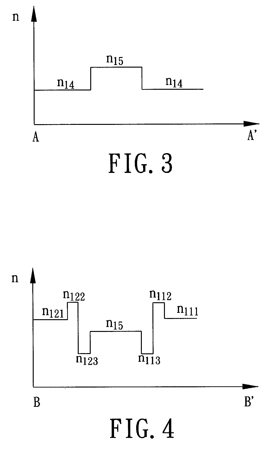
A device for transmitting light signals includes two electrode plates, a spacing structure, a cladding fluid, and a core fluid. The spacing structure, the cladding and core fluids are disposed between the electrode plates. The refractive index of the core fluid is higher than that of the cladding fluid. The core fluid is located on an electrode of one of the electrode plates, and its shape corresponds to the shape of that electrode. The shape and position is changeable and programmable by the electrodes of one of the electrode plates. The core fluid is further surrounded by the cladding fluid, forming an optical waveguide. Via these arrangements, the interface between the core and cladding fluids is much smoother than that between a fluid and a solid, so that the light signals are less likely to scatter while transmitted, in the core fluid. Therefore, the attenuation and reduction of the intensity of the light signals can be decreased. A method for transmitting light signals is also provided.

Description

BACKGROUND OF THE INVENTION[0001]1. Field of the Invention[0002]The present invention relates to a device and a method, in particularly, to a device and a method for transmitting light signals.[0003]2. Description of Related Art[0004]At present, microfluidic systems, also called microfluidic chips, are extensively developed. Since microfluidic systems hold the advantages of rapid reaction rate, high sensitivity, high reproducibility, low cost, low pollution, and so on, they are widely used in various applications such as biological, medical, and photoelectric applications.[0005]In photoelectric application, the microfluidic system can be used as a device for transmitting light signals, i.e., an optical waveguide. This kind of microfluidic system usually has a fixed and grooved microchannel as well as a pump for fluid driving in the microchannel. External light signals (light rays) can be coupled into the fluid filled in the microchannel, and then transmitted within the fluid by the ...

Claims


Application Information

Patent Timeline
Patent Type & Authority Patents(United States)
IPC IPC(8): G02B6/10
CPCG02B6/3538
Inventor FAN, SHIH-KANGCHIEN, CHIA-CHILU, YI-WEN
Owner NAT CHIAO TUNG UNIV
Learn More