Catadioptric projection objective

a technology of catadioptric projection and objective, which is applied in the direction of printing machines, instruments, lighting and heating apparatus, etc., can solve the problems of reducing comparatively high stray light intensity, and cannot be completely prevented, so as to reduce the contrast of the actual image

Active Publication Date: 2013-05-21
CARL ZEISS SMT GMBH
View PDF36 Cites 2 Cited by
  • Summary
  • Abstract
  • Description
  • Claims
  • Application Information

AI Technical Summary

Benefits of technology

[0005]At the lens surfaces of the lenses of the catadioptric projection objective, a specific proportion of the light is reflected on account of the difference in refractive index between air, or the gas filling, and the lens material. Although this reflection can be reduced by antireflection coatings, it cannot be completely prevented. If the projection light reflected at lens surfaces passes into the image plane, this so-called stray light leads to a background illumination that reduces the contrast of the actual image.
[0006]It is an object of the invention, then, to reduce the stray light in such projection objectives.
[0018]Owing to the use of at least six layers composed alternately of material having a high refractive index and material having a low refractive index, it is possible to ensure a reflectivity of less than 0.2% over the angle-of-incidence range of 0° to 30°.
[0023]For correction of the image field curvature and for chromatic correction, the second partial objective can have a plurality of lenses. These lenses which are passed through twice can have surfaces which lead to single reflections. In one embodiment of the invention, the second partial objective has exactly one lens. This reduces the number of surfaces to two surfaces at which single reflections can arise.

Problems solved by technology

Although this reflection can be reduced by antireflection coatings, it cannot be completely prevented.
If the projection light reflected at lens surfaces passes into the image plane, this so-called stray light leads to a background illumination that reduces the contrast of the actual image.
Since the intensity of the reflections is dependent on the product of the reflectivities, single reflections with just one reflection lead to a comparatively high stray light intensity.
The lenses of the second partial objective which are passed through twice are therefore particularly prone to generating stray light in the image plane on account of single reflections.

Method used


Image

  • Catadioptric projection objective
  • Catadioptric projection objective
  • Catadioptric projection objective

Examples


Embodiment Construction

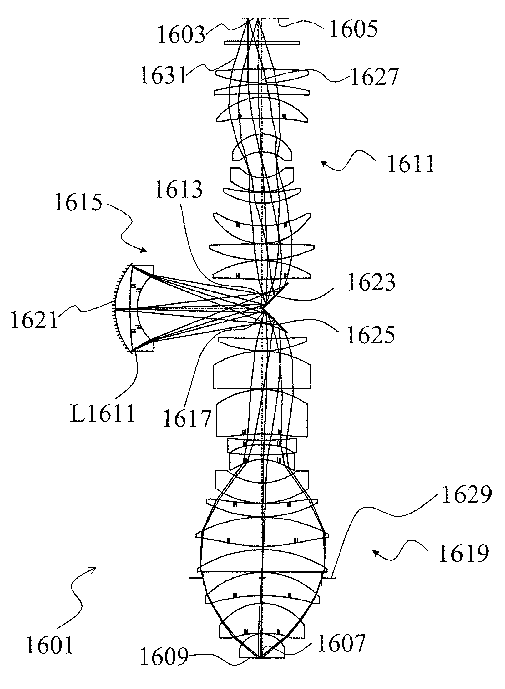
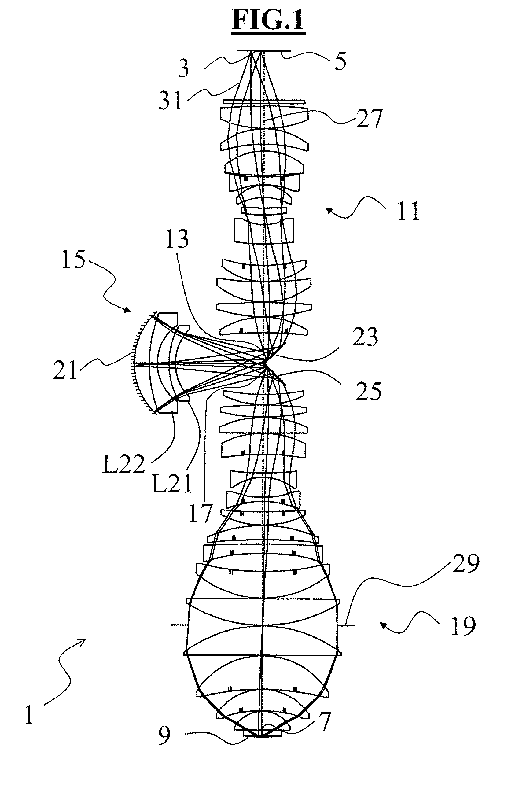
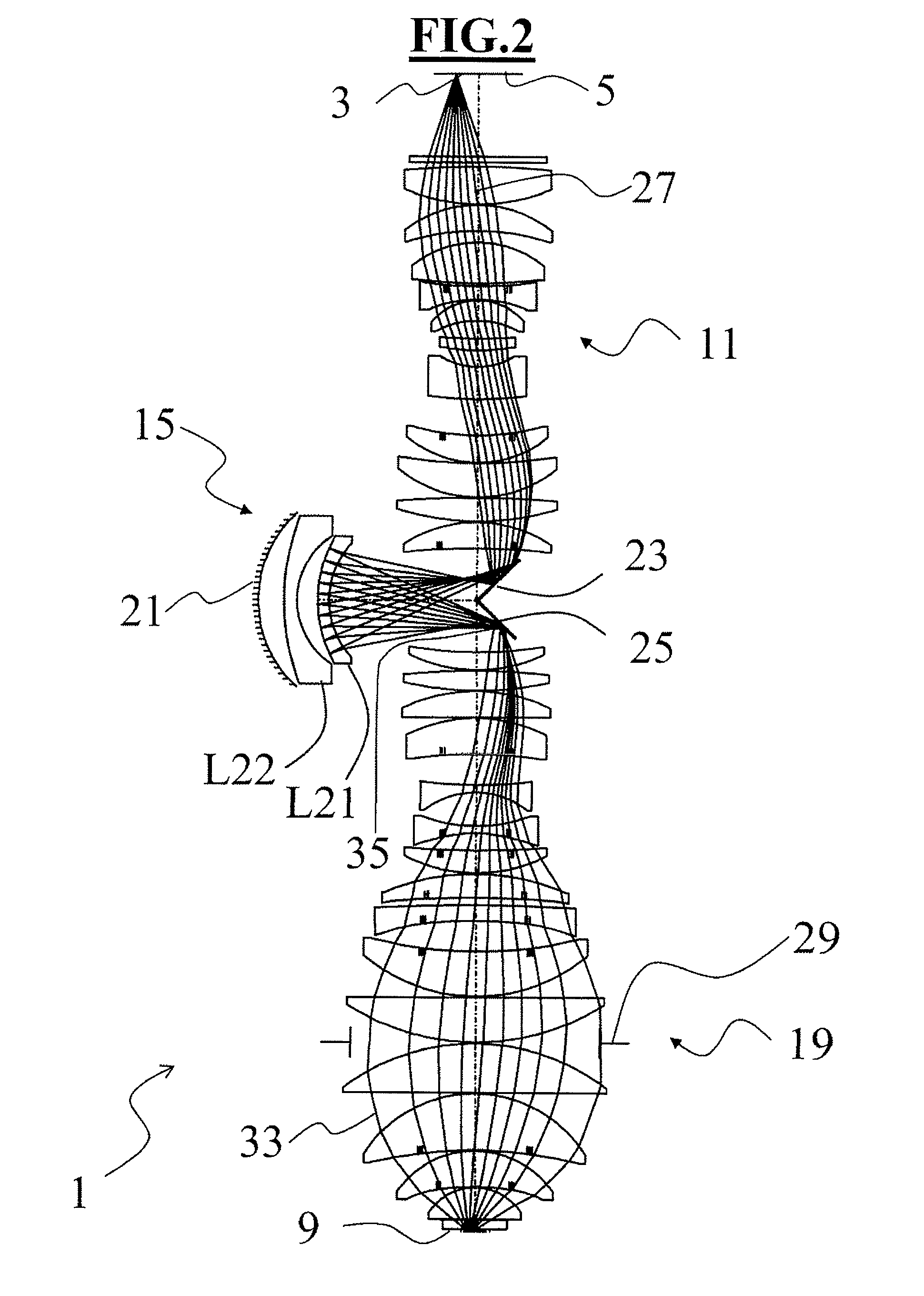
[0057]FIG. 1 shows the lens section of a catadioptric projection objective 1. The optical design of the projection objective 1 has been taken from the patent application US2009 / 0092925A1 in the name of Omura, published on 9 Apr. 2009, and corresponds to FIG. 4 therein. The optical data of the design are summarized in Table 1 in US2009 / 0092925A1. For a more detailed description of the optical design of the projection objective 1, therefore, reference is made to US2009 / 0092925A1, which is hereby incorporated into the present application by reference. The projection objective 1 images the object field 3 in the object plane 5 onto the image field 7 in the image plane 9. It includes a first partial objective 11, which images the object field 3 on to the first real intermediate image 13, the second partial objective 15, which images the first intermediate image 13 on to the second real intermediate image 17, and the third partial objective 19, which images the second intermediate image 17...


PUM

PropertyMeasurementUnit
angle-of-incidenceaaaaaaaaaa
reflectivityaaaaaaaaaa

Abstract

Catadioptric projection objective (1) for microlithography for imaging an object field (3) in an object plane (5) onto an image field (7) in an image plane (9). The objective includes a first partial objective (11) imaging the object field onto a first real intermediate image (13), a second partial objective (15) imaging the first intermediate image onto a second real intermediate image (17), and a third partial objective (19) imaging the second intermediate image onto the image field. The second partial objective is a catadioptric objective having exactly one concave mirror and having at least one lens (L21, L22). A first folding mirror (23) deflects the radiation from the object plane toward the concave mirror and a second folding mirror (25) deflects the radiation from the concave mirror toward the image plane. At least one surface of a lens (L21, L22) of the second partial objective has an antireflection coating having a reflectivity of less than 0.2% for an operating wavelength of between 150 nm and 250 nm and for an angle-of-incidence range of between 0° and 30°. As an alternative or in addition, all the surfaces of the lenses of the second partial objective are configured such that the deviation from the marginal ray concentricity is greater than or equal to 20°.

Description

[0001]The following disclosure is based on German Patent Application No. 10 2009 037 077.3, filed on Aug. 13, 2009, which is incorporated into the present application by reference.FIELD OF AND BACKGROUND OF THE INVENTION[0002]The invention relates to a catadioptric projection objective for imaging an object field in an object plane onto an image field in an image plane including three partial objectives, to a projection exposure apparatus for microlithography including such a projection objective and also to a method for producing semiconductor components and other finely structured components using such a projection exposure apparatus.[0003]The object field is imaged onto a first real intermediate image by the first partial objective of the catadioptric projection objective, the first intermediate image is imaged onto a second real intermediate image by the second partial objective, and the second intermediate image is finally imaged onto the image field in the image plane by the t...

Claims


Application Information

Patent Timeline
Patent Type & Authority Patents(United States)
IPC IPC(8): G02B5/08
CPCG02B17/0892G03F7/70225G03F7/70G02B17/08G03F7/70275G02B13/0015G02B27/0043G03F7/70241G02B1/11G02B17/0896
Inventor EPPLE, ALEXANDERKAMENOV, VLADIMIRGRUNER, TORALFSCHICKETANZ, THOMAS
Owner CARL ZEISS SMT GMBH
Why Eureka
Try Eureka