
Microfluidic extraction and reaction device

a microfluidic and reaction device technology, applied in the direction of gas-gas reaction process, laboratory glassware, separation process, etc., can solve the problem of contamination risk of the transfer from one vessel, not inconsiderable loss of sample material, and transfer of extracted sample material to the microfluidic chip

Inactive Publication Date: 2013-05-28
IMM INST FUR MIKROTECHNIK GMBH
View PDF17 Cites 13 Cited by
  • Summary
  • Abstract
  • Description
  • Claims
  • Application Information

AI Technical Summary

Benefits of technology

The invention is a device that can perform chemical or biochemical assays on a small chip. It has a compressible extraction chamber that prevents clogging of the filter and ensures a sufficient pressure difference between the chambers. The device can be made cheaply using polymer materials and is suitable for disposable use. The integrated lab-on-a-chip system can imitate all the process steps of a chemical or biochemical assay, avoiding the need for numerous costly and often error-prone individual steps.

Problems solved by technology

A particular problem is the transfer of the extracted sample material to the microfluidic chip.
In this way, a not inconsiderable loss of sample material can occur, as well as a risk of contamination for the transfer from one vessel to another.
Moreover, it is not easy to introduce the extract into the chip without loss of fluidic control.
Not least, extraction on a laboratory scale is costly and presupposes large quantities of the starting substances, especially the sample material.
Yet the technical expense of centrifuge extraction is very high.
The centrifuge known from the aforementioned publication contains very many individual parts, some of them moving parts, and is therefore expensive, especially for a onetime use.
Furthermore, the problems associated with the handling of the sample and the extract have not been solved.
The filling of the extractor on the one hand and the transfer of the extracted sample material from the extractor to the centrifuge represent further problems.
In this way, a not inconsiderable loss of sample material can occur, along with a risk of contamination during the transfer from one section of the apparatus to the next.
In summary, it can be said that the performance of the extraction due to the aforesaid reasons is at present cost-intensive, time-consuming, and involves a heightened risk of contamination for personnel and surroundings.
A mere miniaturization of known filtration methods, however, would involve further problems.
Traditional filter arrangements for sample extraction have the drawback that the filter pores very quickly get clogged, which necessarily places a limit on miniaturization.
A large pressure difference during the filtration would moreover lead to a very fast transport of the extract in a connected microfluidic chip, which would jeopardize the fluidic control there.
Also, the pressure strength of the usual microfluidic chips would not be able to withstand the pressures occurring during filtration.

Method used


Image

  • Microfluidic extraction and reaction device
  • Microfluidic extraction and reaction device
  • Microfluidic extraction and reaction device

Examples


Embodiment Construction

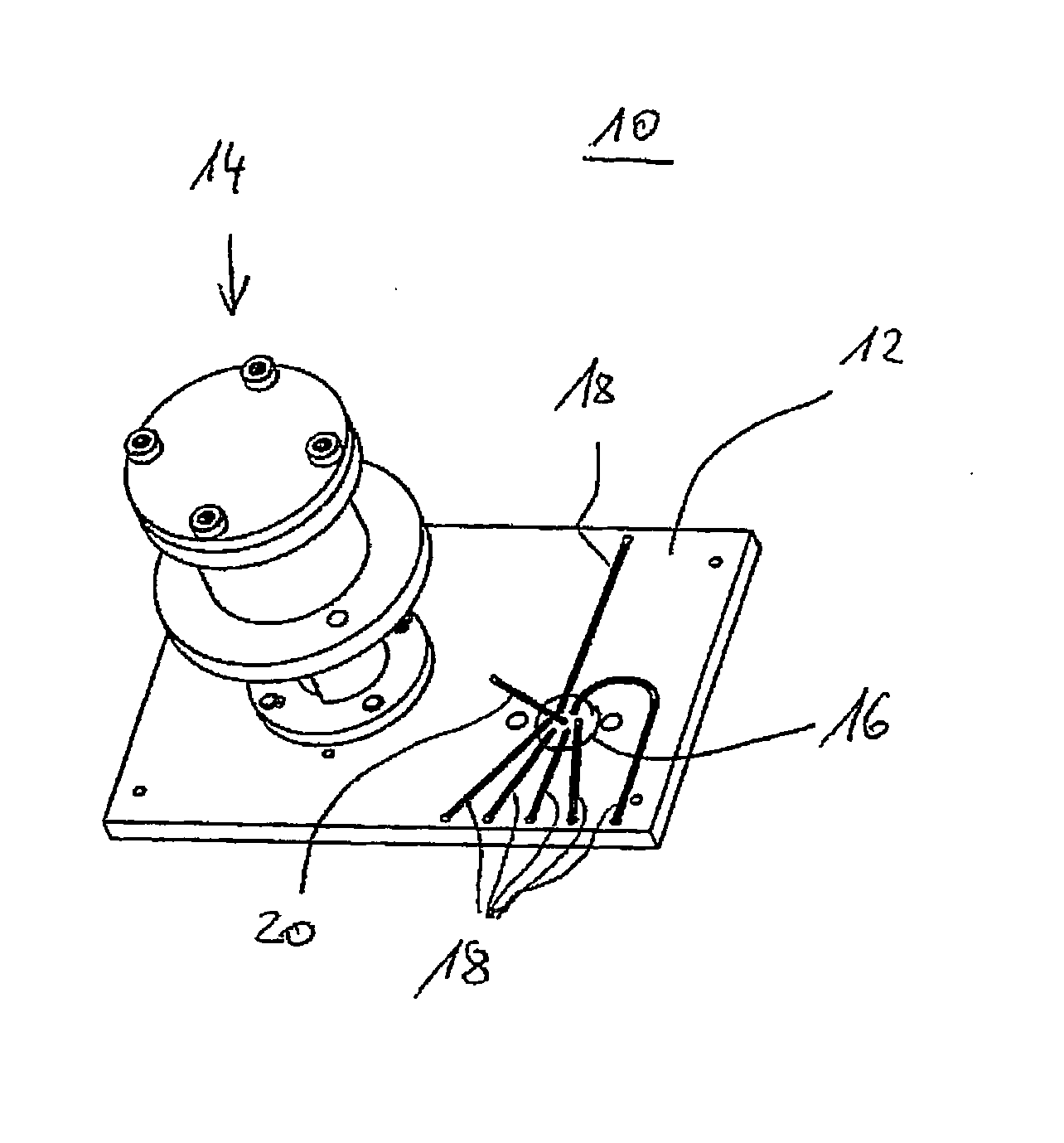
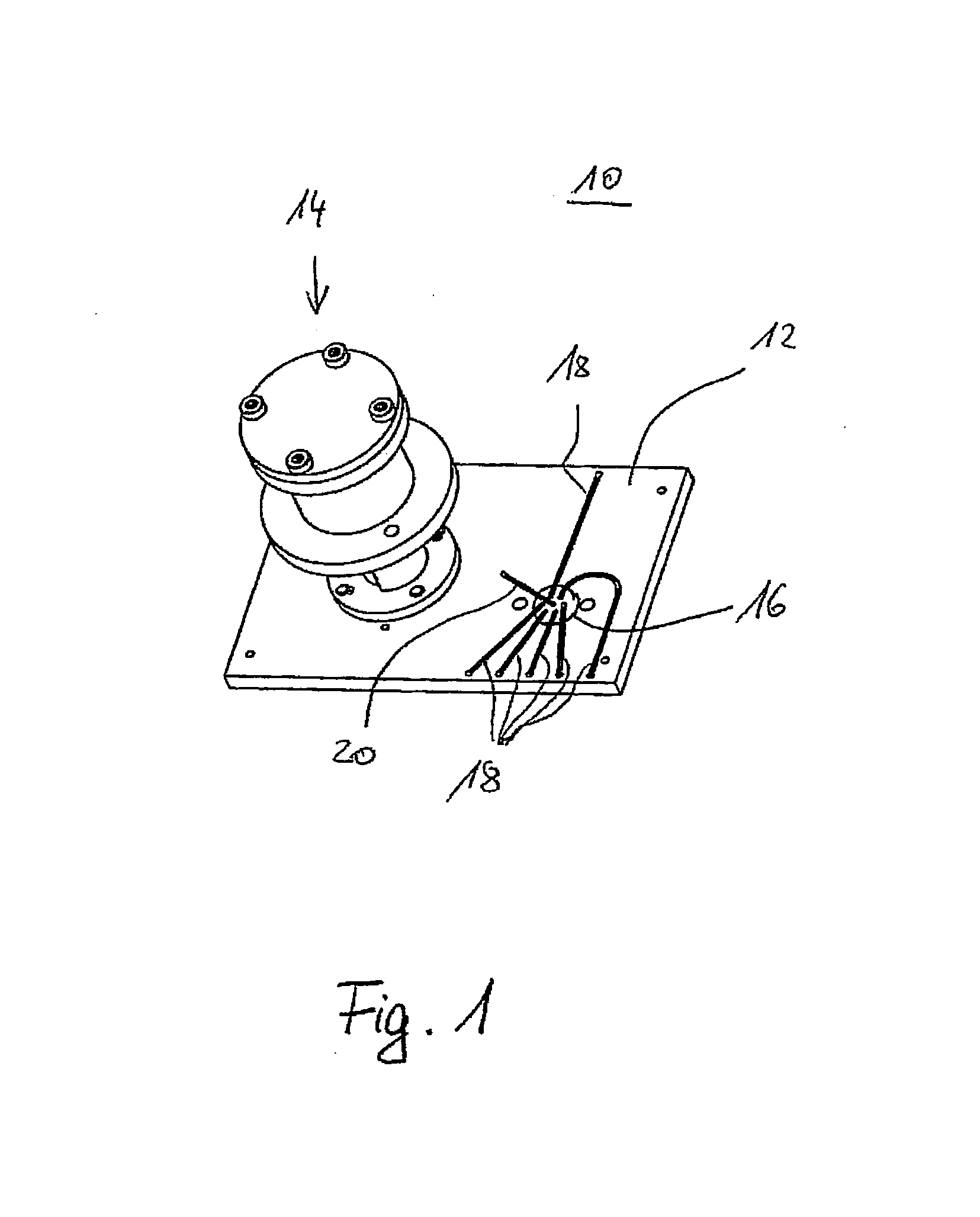
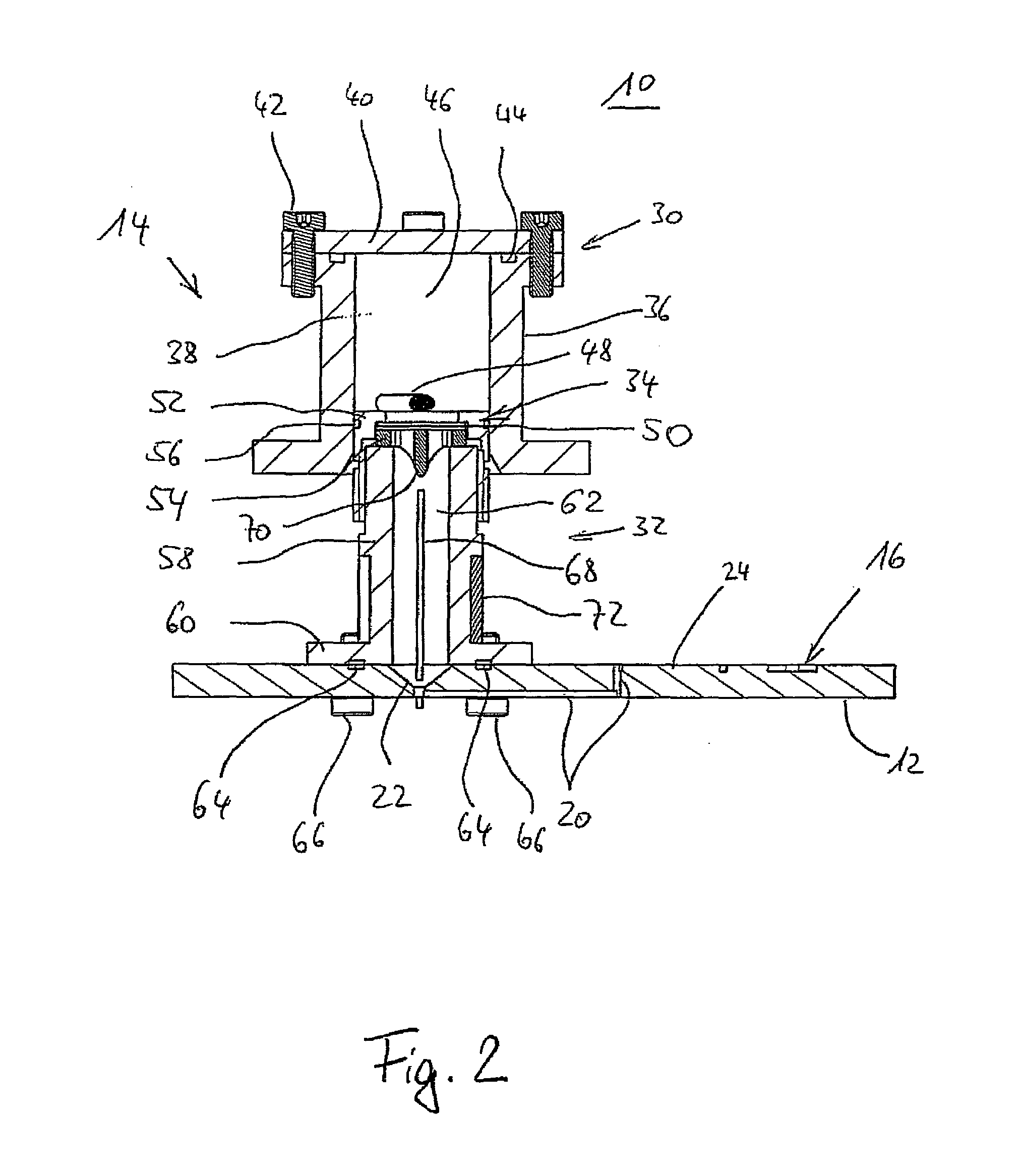
[0039]In FIGS. 1 and 2, the lab-on-a-chip system 10 according to the invention is illustrated by means of one embodiment with a microfluidic chip 12 and a microfluidic arrangement 14 for the extracting and possibly processing of an extract from a sample and for transfer of same in flowable form to the microfluidic chip 12. The microfluidic chip has a valve arrangement 16, which optionally connects one or more inlet and / or outlet lines 18 to a channel 20 or separates them from it. For example, suitable valve arrangements are described in the currently not yet published patent applications DE 10 2008 002 674.3 or DE 10 2008 002 675.1. These have a valve body which can move relative to the chip, which has a sealing surface and defines at least one channel for optional connection and / or separation of fluid lines in the substrate, while the sealing surface of the valve body lies fluid-tight against a sealing surface of the chip. For this, the valve body is pressed against the chip by mea...


PUM

PropertyMeasurementUnit
pore sizeaaaaaaaaaa
pore sizeaaaaaaaaaa
pressuresaaaaaaaaaa

Abstract

A microfluidic arrangement for extracting and optionally processing an extract from a sample and for transferring the extract in flowable form to a microfluidic chip using an extractor with a compressible extraction chamber and at least one opening thereof, a reactor that has a reaction chamber, an inlet opening that communicates with the at least one opening of the extractor, wherein the two openings define a flow path between the chambers, an outlet opening for fluidically connecting to the microfluidic chip and a ventilation opening of the reaction chamber, and having a filter arrangement installed in the flow path between the extractor and the reactor. A lab-on-a-chip system with such a microfluidic arrangement and a microfluidic chip that is rigidly connected to the reactor.

Description

FIELD OF THE INVENTION[0001]The invention concerns a microfluidic arrangement for extracting and optionally processing a flowable extract from a sample and for transferring the extract to a microfluidic chip. Moreover, the invention concerns a lab-on-a-chip system with such a microfluidic chip including the microfluidic arrangement.BACKGROUND OF THE INVENTION[0002]The invention therefore lies in the technical field of extraction of biochemical or chemical analytes, especially DNA / RNA material, protein, cells and / or bacteria from samples, especially solid sample, such as soil samples, foodstuffs and the like, with subsequent reaction. For example, in the extraction of DNA / RNA from samples, the sample is combined with an extraction buffer in known fashion, mixed, and then filtered. The extract or filtrate is then usually subjected to further processing in a suitable container. This can be a molecular biology process (such as labeling during an immunoassay) or lysis during a DNA assay....

Claims


Application Information

Patent Timeline
Patent Type & Authority Patents(United States)
IPC IPC(8): B01J19/00G01N1/00B01D21/00B01L3/02B01L3/00G01N1/18B01J8/00
CPCB01L3/502753G01N1/405Y10T436/25B01L2200/028B01L2200/0605B01L2200/16B01L2300/0681B01L2300/0832B01L2300/0838B01L2300/1827B01L2400/0478B01L2400/0622B01L2400/0644Y10T436/25375Y10T436/255B01L2200/027
Inventor CLAUSSEN, JANWITTAYER, STEPHANSELZER, SUSANNEVON GERMAR, FRITHJOF
Owner IMM INST FUR MIKROTECHNIK GMBH
Learn More