Power control apparatus

a power control and power supply technology, applied in the direction of emergency protective arrangements for limiting excess voltage/current, emergency protective arrangements for automatic disconnection, instruments, etc., can solve the problems of many lives lost, many people injured or killed, and many properties still needlessly damaged or lost to fire, so as to achieve low wattage and minimal heat build-up in the unbalanced load device/resistor

Inactive Publication Date: 2013-05-28
CHILVERS GRAHAM
View PDF15 Cites 17 Cited by
  • Summary
  • Abstract
  • Description
  • Claims
  • Application Information

AI Technical Summary

Benefits of technology

[0016]It will be appreciated that the use of a conventional switching device to switch the supply to the appliance(s) avoids the need to provide any expensive additional contacts. Accordingly, the contacts will already be of a suitably high current rating to handle the current drawn by the appliances. A fire prevention apparatus in accordance with the present invention is thus inexpensive in construction since it utilises off-the-shelf switching devices of the kind which are generally utilised in most domestic and industrial mains supply circuits, to carry the electrical load and perform the actual switching.
[0031]Preferably the load device comprises a resistor creating an unbalanced load always sufficient to activate the switching device. Typically, the current leakage flow or imbalance required to activate a typical switching device is set by many manufactures to be 100 milliamps or less for a time period of less than half a second. Depending on the supply voltage value, an appropriately sized load resistor is used that will result in at least the required current imbalance for the required time, for the switching device to be activated. To allow a small, low wattage (and therefore inexpensive) resistor to be used as the unbalancing load, and in order to prevent the unbalancing load device / resistor from overheating the unbalancing load device / resistor is preferably only connected for a short predetermined time; typically half a second or less. Preferably the unbalancing load device / resistor is repeatedly pulse, connected for a predetermined time in order to ensure that the switching device senses the fault created by the unbalancing load device / resistor and remains off. Thus, if the switching device is manually switched back on before the output from the transducer has been cancelled, the unbalancing load device / resistor will again be pulse connected across the electrical supply by the fault simulation means causing an imbalance, which, when detected by the switching device, will cause the switching device to disconnect the supply again. Also the pulsed application of the unbalancing load device / resistor means that in the event of the switching device being faulty and not switching off after the application of the unbalancing load device / resistor, heat build-up in the unbalancing load device / resistor is minimal.

Problems solved by technology

Many fires are caused by faulty electrical wiring or by electrical appliances malfunctioning or overheating.
Known fire alarm systems save property and many lives.
A great deal of properties are still needlessly damaged or lost to fire.
Many people are also injured or killed.
A large number of fires either occur because the building is empty and a smouldering fire has the opportunity to take hold, or because the occupant(s) simply leave the building when an alarm occurs.
Sometimes occupants are incapable of taking action at the time because, for example, they are asleep, overcome with fumes, too young, panicked, trapped, disabled or affected by drugs or alcohol.
In this manner, a great deal of properties are needlessly damaged or lost to fire.
Many people are also injured or killed.
Some people are injured or killed attempting to stop the outbreak or spread of fire.
Most fires are extinguished using water and a problem with this is that it can be dangerous to extinguish fires using water, since water is a conductor of electricity, thus Firemen run the risk of electrocution.
A disadvantage of the above-mentioned apparatus is that the switch needs to have contacts of a suitably high current rating to handle the current drawn by the appliances.
Furthermore, the switching circuit is expensive in construction and occupies a physical space.
Also, the apparatus is costly to run since the electromagnetic coil is normally energised.
There is also a risk that the coil could overheat and start a fire.

Method used


Image

  • Power control apparatus
  • Power control apparatus
  • Power control apparatus

Examples


Embodiment Construction

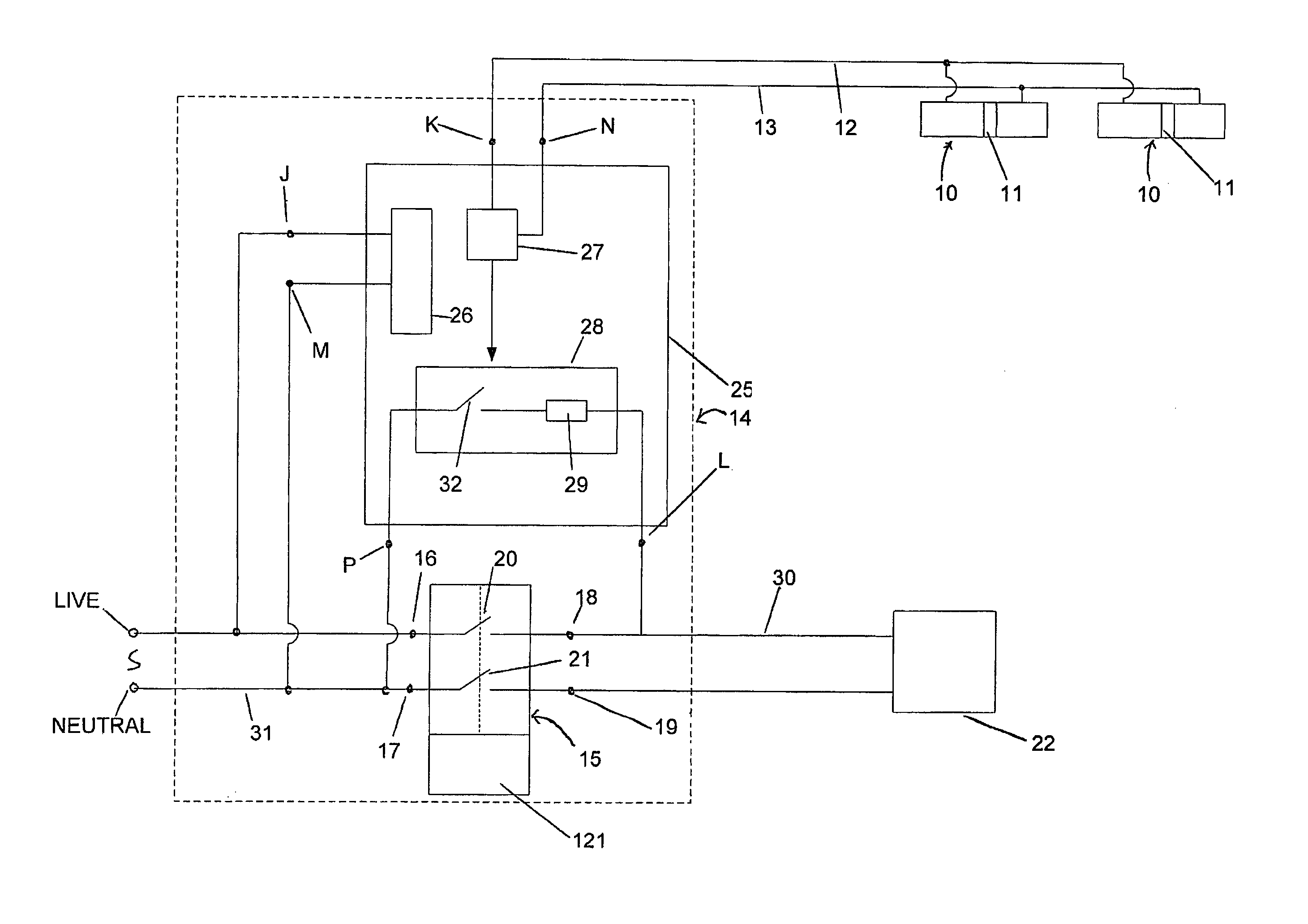
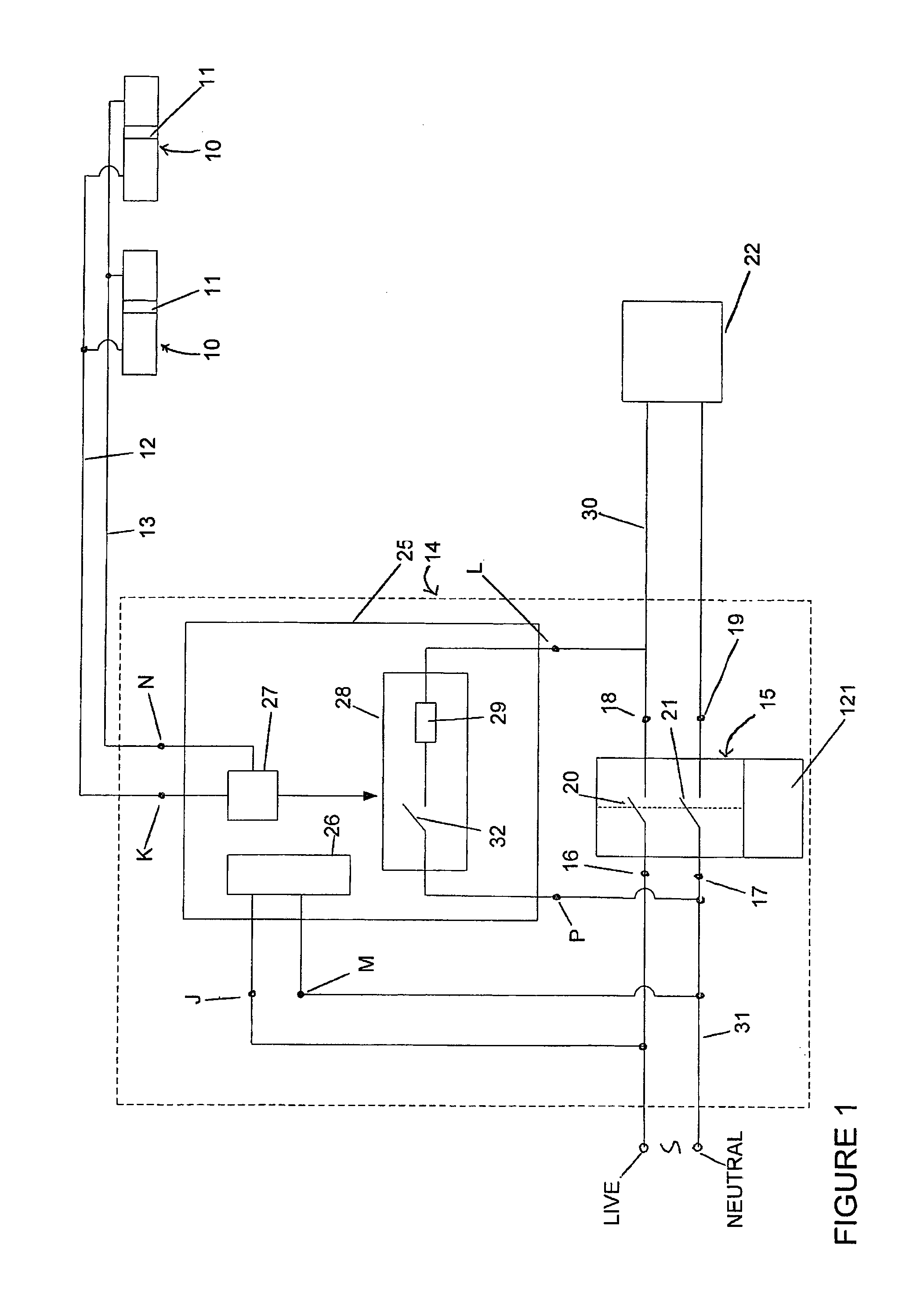
[0037]Referring to FIG. 1 of the drawings, there is shown a fire prevention apparatus comprising one or more smoke detectors 10 connected across a pair of signal wires 12, 13 extending from a remotely-mounted mains consumer unit 14. Each smoke detector 10 comprises a smoke sensor 11. For convenience the mains electrical supply to the smoke detectors 10 is not shown.

[0038]The mains consumer unit 14 comprises one or more residual current devices or so-called RCDs 15 mounted on a rail inside the housing of the mains consumer unit 14. Each RCD 15 comprises a pair of input terminals 16, 17 for respectively connecting to the live and neutral of the mains supply S. Each RCD 15 also comprises a pair of output terminals 18, 19 which are connected to respective input terminals 16, 17 via ganged switches 20, 21. An appliance circuit 22 is connected across the output terminals 18,19 so that the live and neutral of the mains supply S is applied thereto when the switches 20,21 of the RCD 15 are c...


PUM


Abstract

A power control apparatus comprises a transducer having an output (12,13) which is connected to a remotely activated device (25) mounted in a mains consumer unit (14). When a predefined parameter is detected, the device (25) is activated to connect a load (29) between the switched live output (18) of a residual current device RCD (15) and the neutral input (17) thereof, thereby creating an imbalanced current flow on the live and neutral output terminals (18,19) of the RCD (15) which causes contacts (20,21) inside the RCD (15) to disconnect the supply to an appliance circuit (22).

Description

BACKGROUND OF THE INVENTION[0001]1. Field of the Invention[0002]This invention relates to a power control apparatus.[0003]2. Related Background Art[0004]Many fires are caused by faulty electrical wiring or by electrical appliances malfunctioning or overheating. Many fires are also caused by overheating liquids and solids (such as food and drink), which are being heated or cooked using a cooking appliance. Generally, before a fire starts, the source of the fire normally emits smoke. This smoke can be detected by a fire alarm system or smoke detector(s) to warn the occupants of a building that smoke has been detected. The occupants may take remedial action upon hearing the alarm to address the cause of smoke before a fire starts, for example by switching off the appliance or unplugging the electrical appliance or by removing the source of heat from a liquid or solid which is being heated or cooked.[0005]Known fire alarm systems save property and many lives. A great deal of properties ...

Claims


Application Information

Patent Timeline
Patent Type & Authority Patents(United States)
IPC IPC(8): H01H83/00
CPCH02H3/334H02H5/047G08B17/06H02H3/33
Inventor CHILVERS, GRAHAM
Owner CHILVERS GRAHAM
Why Eureka
Try Eureka