Electromagnetic position and orientation sensing system

a technology of position and orientation, applied in the field of electromagnetic position and orientation sensing system, can solve problems such as undesirable connection

Inactive Publication Date: 2013-05-28
BROWN UNIVERSITY
View PDF57 Cites 35 Cited by
  • Summary
  • Abstract
  • Description
  • Claims
  • Application Information

AI Technical Summary

Benefits of technology

[0014]In another embodiment, the transmitter included in the presently disclosed magnetic tracking system employs a digital tuning technique that compensates for component variation so that precision component values are not required to achieve resonance. In accordance with this embodiment, the transmitter includes a plurality of resonant circuits, first and second sets of digitally controllable switches, first and second sets of pulse generators, sense circuitry, and a controller. Each resonant circuit has a transmitter coil, a resonating capacitor electrically coupled in parallel with the transmitter coil, and a tuning capacitor connected by a corresponding second digitally controllable switch in parallel with the resonating capacitor. Each of the first set of digitally controllable switches is electrically coupled in series between one end of one of the resonant circuits and one terminal of a power source. Each of the other ends of the resonant circuits is electrically coupled to the other terminal of the power source. Each of the first set of pulse generators generates periodic digital pulses for controlling one of the first set of digitally controllable switches, thereby sustaining continuous, periodic, and substantially sinusoidal currents in the resonant circuits. In response to the respective continuous, periodic, and substantially sinusoidal currents, the transmitter coils generate electromagnetic fields defining a reference coordinate system for the magnetic tracking system. Each of the second set of digitally controllable switches is electrically coupled in series between one end of one of the tuning capacitors and the other terminal of the power source. The other end of each tuning capacitor is attached to its corresponding resonant circuit at the same end as the first digitally controllable switch. Each of the second set of pulse generators generates digital pulses for controlling one of the second set of digitally controllable switches, thereby switchably coupling the respective tuning capacitors in parallel with the respective resonating capacitors. The sense circuitry measures the currents sustained in the resonant circuits, and the controller controls the timing of the digital pulses generated by the second set of pulse generators based on the current measurements of the sense circuitry, thereby controlling operation of the second set of digitally controllable switches for reducing the power consumption of the resonant circuits. Tuning for minimum power also compensates for changes in transmitter operating frequency should that be necessary to avoid interference between independent transmitters operating near each other.
[0019]In yet another embodiment, the presently disclosed magnetic tracking system is configured so that the transmitter can fit inside a thin flat box, thereby facilitating embedding the transmitter box into the user's environment, and increasing the likelihood that the transmitter box would be viewed by the user as a feature of, rather than an obstacle in, that environment. In accordance with this embodiment, the magnetic tracking system includes a coil assembly having a generally flat transmitter housing with a top surface generally defining a top surface plane, and a plurality of transmitter coils fixedly positioned within the transmitter housing. Each of the transmitter coils has a center and coil turns that generally lie in a plane substantially parallel to the top surface plane. In addition, the center of each transmitter coil is displaced from the centers of the other transmitter coils.

Problems solved by technology

1. separating the three signals received at each receiver coil to determine their three individual amplitudes;
2. doing that separation without any connection from the transmitter clock source to the receiver, as such, a connection is undesirable for reasons of cost and connectivity;
3. generating the transmitter electromagnetic fields at acceptable cost, and tolerant to variations in component values from manufacturing tolerance, aging, and temperature change;
4. providing a mechanism by which any receiver may be used with any transmitter without prior calibration by determining channel calibration from ordinary measurement data; and
5. compacting the transmitter coils for some applications so that they are coplanar yet can still generate electromagnetic fields that define a two or three-dimensional coordinate system.

Method used


Image

  • Electromagnetic position and orientation sensing system
  • Electromagnetic position and orientation sensing system
  • Electromagnetic position and orientation sensing system

Examples


Embodiment Construction

[0037]The disclosure of U.S. Provisional Patent Application No. 61 / 173,315 filed Apr. 28, 2009, entitled ELECTROMAGNETIC POSITION AND ORIENTATION SENSING SYSTEM is incorporated herein by reference in its entirety.

[0038]An improved system and method of determining the position and orientation of a remote object is disclosed that avoids the drawbacks of conventional remote object position and orientation determining techniques.

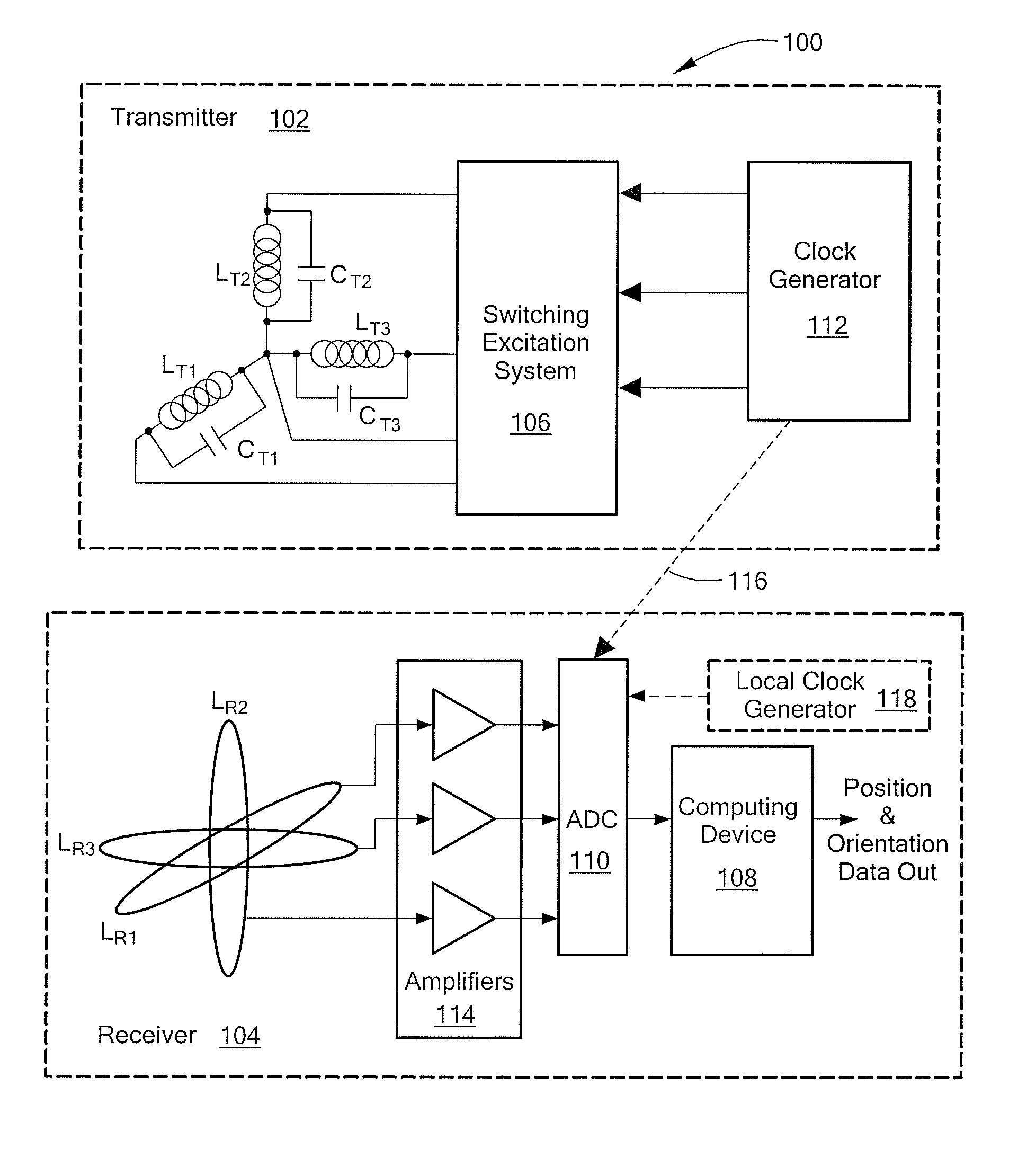
[0039]FIG. 1 depicts an illustrative system 100 for measuring the position and orientation of a remote object. As shown in FIG. 1, the system 100 includes a stationary transmitter 102 and a receiver 104. The remote object (not shown) is associated with the receiver 104. For example, the remote object may be attached to, mounted on, or otherwise coupled to the receiver 104. The stationary transmitter 102 is operative to establish a reference coordinate system. In one embodiment, the transmitter 102 includes a set of three mutually perpendicular coils LT1, LT2, LT...


PUM

PropertyMeasurementUnit
conduction angleaaaaaaaaaa
closure timeaaaaaaaaaa
conduction anglesaaaaaaaaaa

Abstract

Magnetic tracking systems and methods for determining the position and orientation of a remote object. A magnetic tracking system includes a stationary transmitter for establishing a reference coordinate system, and at least one receiver. The remote object is attached to, mounted on, or otherwise coupled to the receiver. The transmitter can include a set of three mutually perpendicular coils having a common center point, or a set of three coplanar coils with separate centers. The receiver can include a set of three orthogonal coils. The position and orientation of the receiver and the remote object coupled thereto is determined by measuring the nine mutual inductances between the three transmitter coils and the three receiver coils. The magnetic tracking system provides reduced power consumption, increased efficiency, digital compensation for component variation, automatic self-calibration, automatic synchronization with no connections between transmitter and receiver, and rapid low-cost implementation.

Description

CROSS REFERENCE TO RELATED APPLICATIONS[0001]This application claims benefit of U.S. Provisional Patent Application No. 61 / 173,315 filed Apr. 28, 2009, entitled ELECTROMAGNETIC POSITION AND ORIENTATION SENSING SYSTEM.STATEMENT REGARDING FEDERALLY SPONSORED RESEARCH OR DEVELOPMENT[0002]Not applicableBACKGROUND OF THE INVENTION[0003]The present application relates to an improved system and method of determining the position and orientation of a remote object.[0004]A typical system for determining the position and orientation of a remote object includes a receiver with three receiver coils that are orthogonal to one another, and a transmitter with three transmitter coils that carry sinusoidal currents operative to generate electromagnetic fields defining a reference coordinate system. The receiver, which is associated with the remote object, is operative to measure the voltage induced in each receiver coil by the electromagnetic fields. There are nine such induced voltages, and the out...

Claims


Application Information

Patent Timeline
Patent Type & Authority Patents(United States)
IPC IPC(8): G01B7/14G01B7/30H01F5/00
CPCG01B7/004G01B7/14G01B7/003G01D5/2086G01R35/005G01D5/204G01V13/00G01V3/081
Inventor SILVERMAN, KENNETH J.
Owner BROWN UNIVERSITY
Why Eureka
Try Eureka