Insulated fiber sensor apparatus and method

a fiber sensor and fiber technology, applied in the direction of resistor details, resistor housing/enclosement/embedding, instruments, etc., can solve the problems of reducing the mechanical performance of composites during the service life of composite structures, not having effective and efficient methods to measure the deformation (or strain) of fibers

Active Publication Date: 2013-05-28
HSIAO KUANG TING
View PDF14 Cites 21 Cited by
  • Summary
  • Abstract
  • Description
  • Claims
  • Application Information

AI Technical Summary

Problems solved by technology

Notwithstanding the brilliant theoretical properties of composite materials, the true material properties observed in the real world fall short of those theoretically predicted.
Importantly, as the major load-carrying system is the fiber, it follows that any change in the load behaviour of the fiber system will also cause a change (typically a reduction) in the mechanical performance of a composite during the service life of a composite structure.
Although there are many prior art ways to measure the total deformation of a composite structure, Applicant has determined that there are not any effective and efficient methods that can measure the deformation (or strain) of a fiber inside a composite during the use of the composite structure.
The technical challenge is caused by (1) the typically small micro-size diameter of the fiber, (2) the distinctive thermal and mechanical properties between the fiber and matrix, and (3) the presently unknown and unmeasurable interface behavior between the fiber and the matrix.
The residual strain tends to affect both the physical and mechanical characteristics of the composite materials and is responsible for dimensional instability and an increase in damage to and premature failure of the composite.
This results in compressive residual strains in the fiber and tensile strains in the surrounding polymer matrix, and can also cause macro-mechanical or lamination residual stresses.
A disadvantage of this method is the requirement of thin composite layers with low fiber volume.
There is a problem however.
In addition, certain amorphous fibers have a very week Raman response and can not be readily used as intrinsic stress or strain sensors, for example glass.
The disadvantage of this method is that in order to accurately quantify the residual stresses present more information is required.
The disadvantage of this method is that a cavity (and, as a consequence, a weakness) is included in the laminate and the diameter of the sensor is so large that stress concentrations may arise.
Furthermore, the EFPI sensor is prone to failure caused by thermal residual stresses alone.
The disadvantage of utilizing optic fiber sensors is that when it is embedded perpendicular to the fiber, an eye-shaped defect results thereby causing a significant stress concentration and decrease in mechanical properties.
The key disadvantage of this technique is that it either gives information on the surface properties of the sample only or, at best, only a thin portion of the sample.
Although accurate, this method only gives information of the residual strain state on the surface.
One drawback of the curvature method is that values of curvature may show variations for equal laminates under similar conditions.

Method used


Image

  • Insulated fiber sensor apparatus and method
  • Insulated fiber sensor apparatus and method
  • Insulated fiber sensor apparatus and method

Examples


Embodiment Construction

Definitions

[0042]Terms as Used Herein:

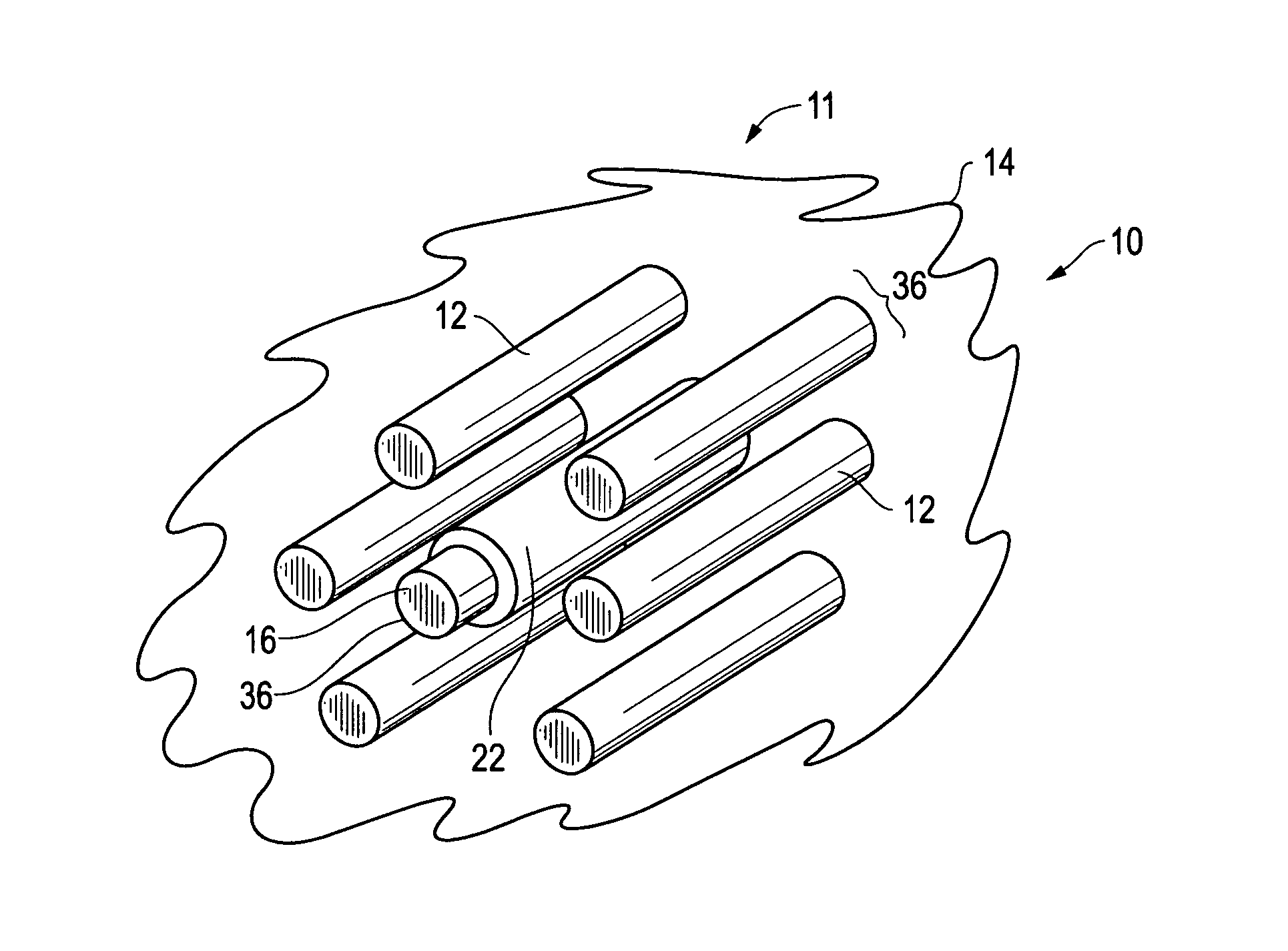
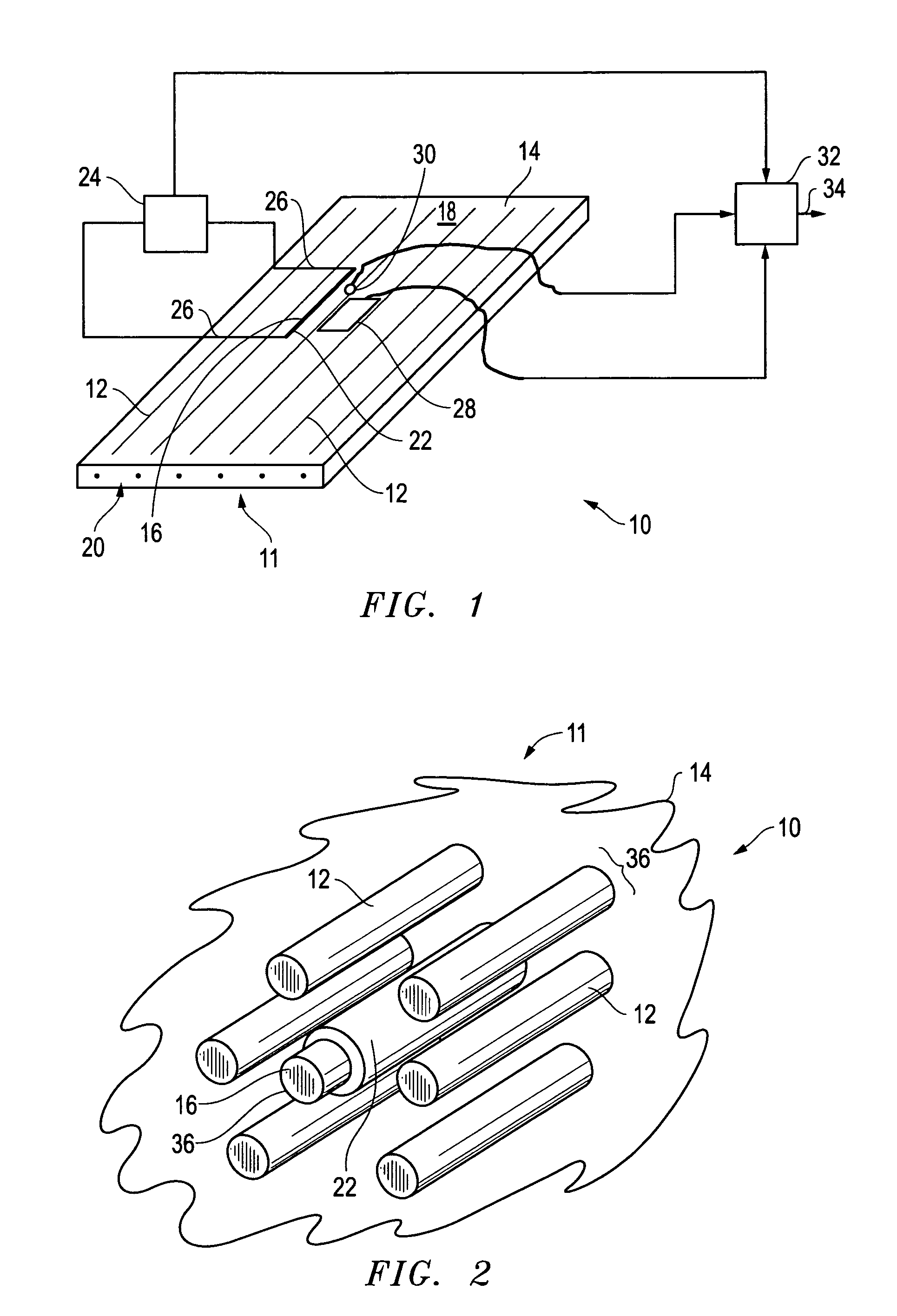
The term “in-situ” is defined as the event occurs and is measured at nearly the exact or exact physical location of the fiber sensor in the composite.

The term “micro-level” is defined as the scope of length scale the same or nearly the same as the fiber whose diameter is of micrometer scale.

The term “carbon fiber” is defined as the fiber made of nearly pure carbon or graphite and its diameter is of micrometer scale.

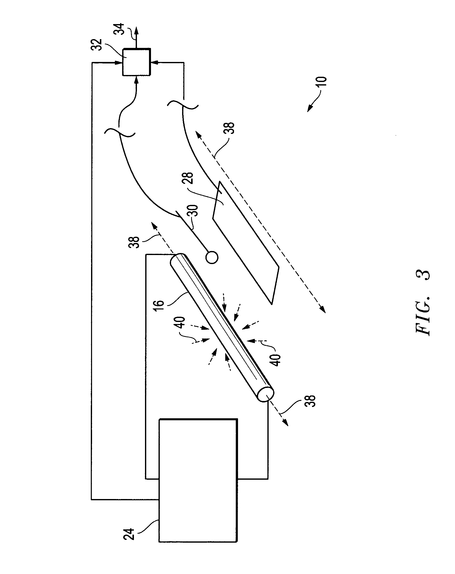
The term “sensor” is defined as an apparatus and method for detecting or measuring physical changes of an object or system.

The term “coating” is defined as a thin layer of polymer, ceramic, glass, diamond or the like, deposited on the fiber.

The term “insulation layer” is defined as the polymer coating, ceramic, glass, diamond or the like, deposited on the fiber to prevent electrical current leak from being conducted between the coating insulated fiber and its surroundings.

The term “strain” is defined as the change in distance between ...


PUM

PropertyMeasurementUnit
Gage Factoraaaaaaaaaa
diameteraaaaaaaaaa

Abstract

An insulated fiber sensor apparatus is used in a composite that includes a number of fibers in a matrix. An insulated fiber is connected with the composite and is covered with insulation such that the insulation separates the insulated fiber from the matrix and from the number of fibers in the matrix. Further, a measurement device is connected with the insulated fiber. According to one aspect of the invention, the fibers are carbon fibers.

Description

CROSS REFERENCE TO RELATED APPLICATION[0001]This application claims the benefit of previously filed U.S. provisional patent application No. 61 / 214,988 filed Apr. 30, 2009 for a “Novel carbon fiber sensor for in-situ carbon fiber strain monitoring”. The Applicant hereby claims the benefit of this provisional application under 35 U.S.C. §119. The entire content of this provisional application is incorporated herein by this reference.FIELD OF THE INVENTION[0002]This invention relates to an insulated fiber sensor apparatus and method. In particular, in accordance with one embodiment, the invention relates to an insulated fiber sensor apparatus in a composite including a number of fibers and a matrix. An insulated fiber is connected with the composite and is covered with insulation such that the insulation separates the insulated fiber from the matrix and from the number of fibers in the matrix. Further, a measurement device is connected with the insulated fiber. According to one aspect ...

Claims


Application Information

Patent Timeline
Patent Type & Authority Patents(United States)
IPC IPC(8): G01R27/08G01R27/00G01R27/02H01C1/02
CPCG01M5/0083G01L1/205B29C70/54
Inventor HSIAO, KUANG-TING
Owner HSIAO KUANG TING
Why Eureka
Try Eureka