Ultra-wide band (UWB) artificial magnetic conductor (AMC) metamaterials for electrically thin antennas and arrays

an artificial magnetic conductor and antenna technology, applied in the direction of electrically short antennas, antenna feed intermediates, antennas, etc., can solve the problems of inability to achieve any practical useful bandwidth at lower frequencies, the amc system is no longer tuned to receive the incident electromagnetic field, and the fraction of bandwidth is narrow. , to achieve the effect of minimizing power reflection, maximizing received power transfer, and reducing the size of the antenna

Inactive Publication Date: 2013-05-28
FLUHLER HERBERT U
View PDF5 Cites 297 Cited by
  • Summary
  • Abstract
  • Description
  • Claims
  • Application Information

AI Technical Summary

Benefits of technology

[0014]With a traditional array of antenna elements, narrow band or UWB, one would usually connect a feed line to the feed of each antenna element. Nominally the feed line would have a characteristic impedance equal to the feed impedance in order to maximize the received power transfer into or out of the feed line, and minimize reflection of power from the feed due to any impedance mismatch. In our case, we actually want the feed to reflect the received power so that it reradiates back out of the antenna elements. However, we want that reflection to occur with a specific phase, and ideally that phase is near zero degrees of phase. So, instead of placing a matched port at the feed point of the each UWB antenna element in our new AMC array, an explicit open circuit is left in the design. Hence the operational concept is that the UWB antenna elements receive the energy from the wave, it gets converted to a current, and then that current moves to the feed points. But instead of encountering a matched load, the currents encounter an open feed point, which reflects the power back with a zero phase reflection angle just like an open microstrip stub, since an open RF circuit produces a zero phase change as opposed to a short circuit which would produce a 180 degree phase change. This radiation is then reradiated back out the array structure with a phase substantially closer to zero phase than not.
[0015]With respect to the second part of the operation of our new AMC invention, it must be recognized that an array of closely spaced antenna elements (narrow band or UWB) will exhibit mutual coupling between the elements. This mutual coupling produces a coupled dipole array type of structure that changes the behavior somewhat, particularly toward lower frequencies (the coupling producing a effectively larger antennas structure). The coupling can be complex to model analytically and therefore electromagnetic simulation codes such as Finite Difference Time Domain (FDTD) and ot

Problems solved by technology

A central limitation of all AMCs demonstrated to date is narrow fractional bandwidth (typically less than 10% and often less than a couple of percent bandwidth), and a progressive difficulty in achieving any practical useful bandwidth at lower frequencies (a couple of GHz or lower).
However, as one moves off the resonant frequency of these traditional AMC structures, the AMC system is no longer tuned to receive the incident electromagnetic field.
If one tries only to modify the AMC circuit for larger AMC bandwidth, this results in larger inductance in the AMC circuit which then results in a larger impedance mismatc

Method used


Image

  • Ultra-wide band (UWB) artificial magnetic conductor (AMC) metamaterials for electrically thin antennas and arrays
  • Ultra-wide band (UWB) artificial magnetic conductor (AMC) metamaterials for electrically thin antennas and arrays
  • Ultra-wide band (UWB) artificial magnetic conductor (AMC) metamaterials for electrically thin antennas and arrays

Examples


Embodiment Construction

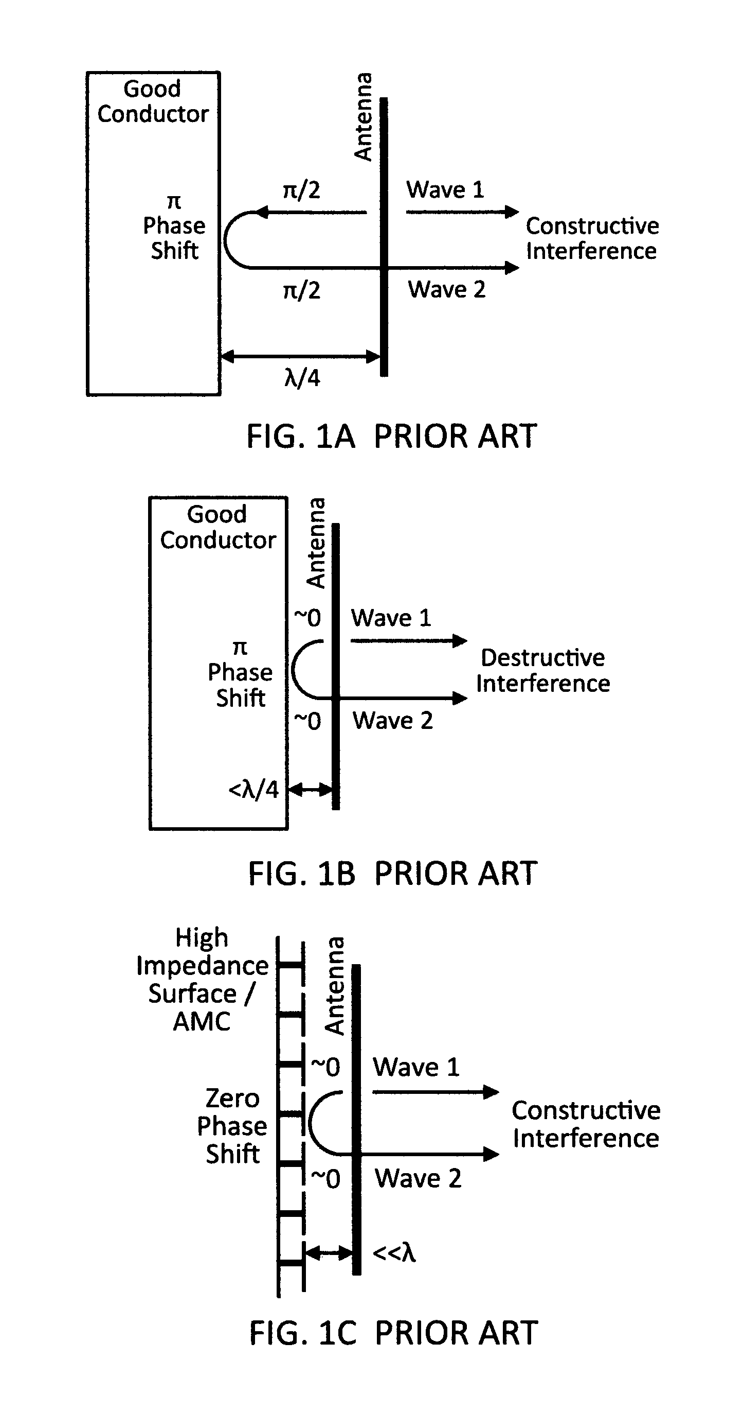
[0034]FIG. 1A shows a traditional quarter wave standoff of an actively fed antenna or thin array above a PEC backplane. The backward traveling wave 2 propagates a quarter wavelength (90 degrees) to the left, reflects from the PEC backplane with a 180 degree (pi radians) phase shift, then travels back to the antenna to meet up with a forward traveling (to the right) direct path wave emanating from the antenna. Because of the resulting 360 phase shift on the previously backward traveling, now reflected wave 2, it is in phase with the direct path wave 1 emanating from the antenna so that both now travel in phase to the right. This results in them adding constructively providing a doubling of the amplitude and a resulting quadrupling (6 dB) of the power / gain on boresight (i.e. directly to the right in the figure). If one were to observe the gain at angles off boresight, one would see lower relative gain off boresight versus an antenna without a backplane. This is because of the differen...


PUM


Abstract

This disclosure demonstrates a new class of Ultra-Wide Band (UWB) AMC with very large fractional bandwidth (>100%) even at lower frequencies (<1 GHz). This new UWB AMC is enabled by recognizing that any AMC must be an antenna in order to accept the incident radiation into the circuit. Therefore, by using UWB antenna design features, one can make wide band AMCs. Additionally, by manipulation of the UWB AMC element design, a 1/frequency dependence can be obtained for instantiating the benefits of a quarter wave reflection over a large UWB bandwidth with a single physical thickness.

Description

CROSS REFERENCE TO RELATED APPLICATIONS[0001]This application claims the benefit of provisional application No. 61 / 212,698, filed Apr. 15, 2009, this provisional application being incorporated in its entirety herein by reference.FEDERALLY SPONSORED RESEARCH[0002]This invention was created partially with support from the United States Government, Department of Defense, U.S. Army, under Small Business Innovative Research (SBIR) program contract W911QX-08-C-0096. The United States has certain SBIR rights in the invention as described in the SBIR authorization statute.FIELD OF THE INVENTION[0003]This invention relates to a subset of Radio Frequency (RF) Metamaterials, specifically Artificial Magnetic Conductors (AMC) instantiated with Ultra-Wide Band (UWB) Artificial Dielectric Materials (ADM) for the purpose of enabling thinner wide band antennas and antenna arrays.BACKGROUND OF THE INVENTION[0004]Artificial Magnetic Conductors (AMC) are theoretical materials that reflect electromagnet...

Claims


Application Information

Patent Timeline
IPC IPC(8): H01Q15/02
CPCH01Q15/0086
Inventor FLUHLER, HERBERT U.
Owner FLUHLER HERBERT U
Why Eureka
Try Eureka