
Carbonating device, method of use, and related discharge and cap assemblies

Inactive Publication Date: 2013-06-04
GOBUBL
View PDF10 Cites 6 Cited by
  • Summary
  • Abstract
  • Description
  • Claims
  • Application Information

AI Technical Summary

Benefits of technology

The present invention addresses the problem of excess gas wastage and the risk of injury from high gas pressure in carbonating devices. The invention provides a carbonating device that automatically prevents excess release of gas and a trigger pressure regulator to control the inlet valve and exit valve, and a carbonating pressure regulator to control the exit valve. The device can be formed from two separate assemblies, allowing for carbonation of multiple vessels, or a single device with a carbonating piston controlled by the carbonating pressure regulator. The technical effects of this invention are improved safety and efficiency in carbonating processes.

Problems solved by technology

Carbonated drinks are known to loose freshness once a part of the contents of the beverage has been consumed, because the remaining liquid begins to lose its CO2 content.
As more of the drink is consumed, more CO2 is lost.
The remaining amount of beverage is then still substantial, but not good to drink.
Furthermore, venting the CO2 to the atmosphere when a predetermined pressure is reached within the beverage vessel is undesirable.
If a large amount of CO2 is released from the cartridge in one go, the discharge of CO2 can lead to excessive cooling of the cartridge.
Thus there is a danger of freezer burn when coming into contact with the cartridge.
Furthermore, if skin comes into direct contact with the CO2, there is a danger of burning.
Moreover, if the high flow rate is maintained, there is a danger that the valve controlling exit of CO2 from the canister may be compromised by icing at the point of discharge.
The high flow rate of the expelled CO2 gas is also hard to control.
This leads to the gas being vented straight out of the pressure release valve, which leads to excessive wastage of the CO2.
This is not cost effective.
Furthermore, known over pressure valves that vent to the atmosphere do not particularly reduce the flow rate from the canister, thus there is a possibility of the discharge from the over pressure valve being directed by the incompetent person into the eyes or face of themselves or another.
Also there is a danger that the discharge from an over pressure valve could come into contact with the user or bystander.

Method used


Image

  • Carbonating device, method of use, and related discharge and cap assemblies
  • Carbonating device, method of use, and related discharge and cap assemblies
  • Carbonating device, method of use, and related discharge and cap assemblies

Examples


Embodiment Construction

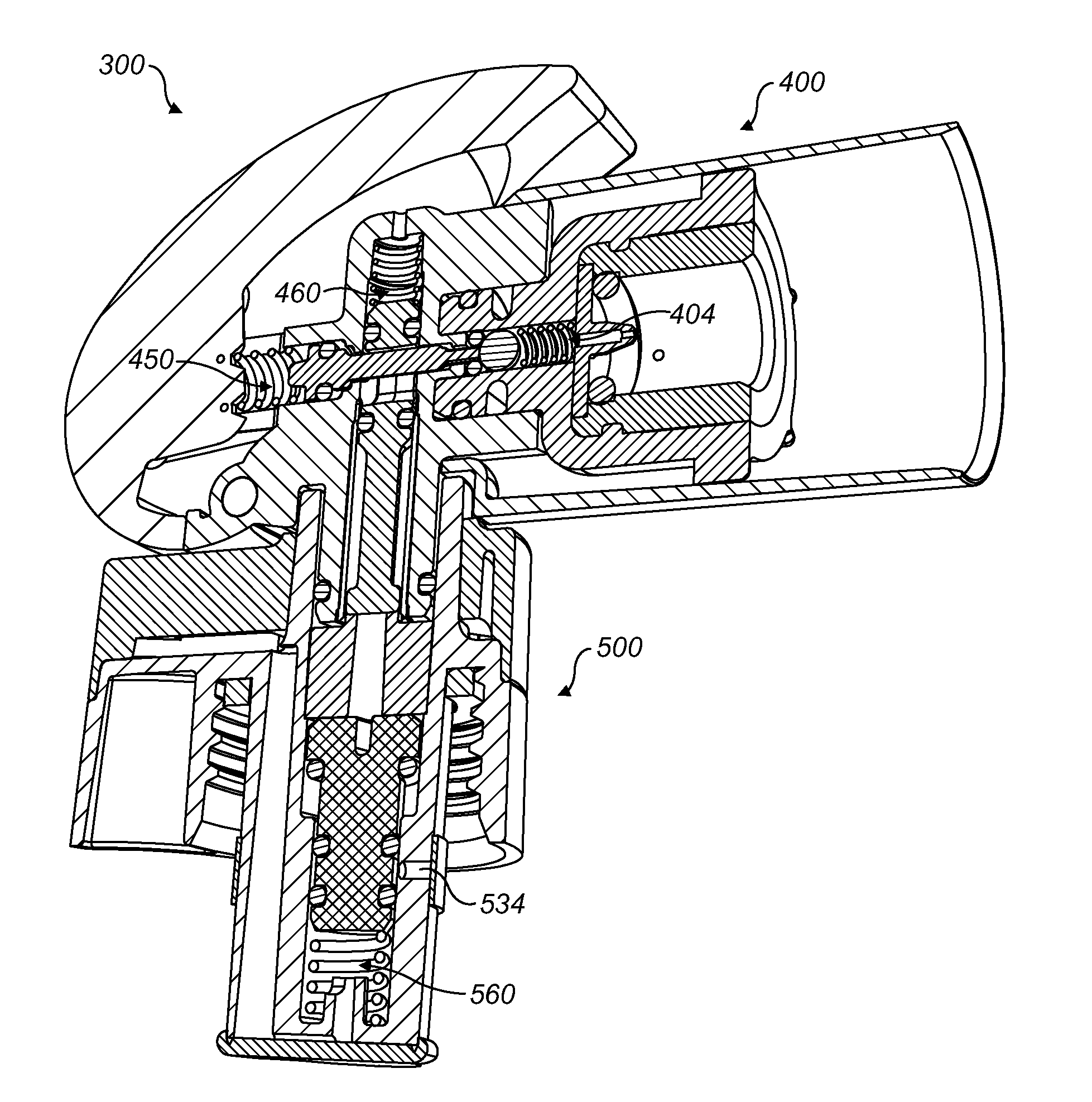
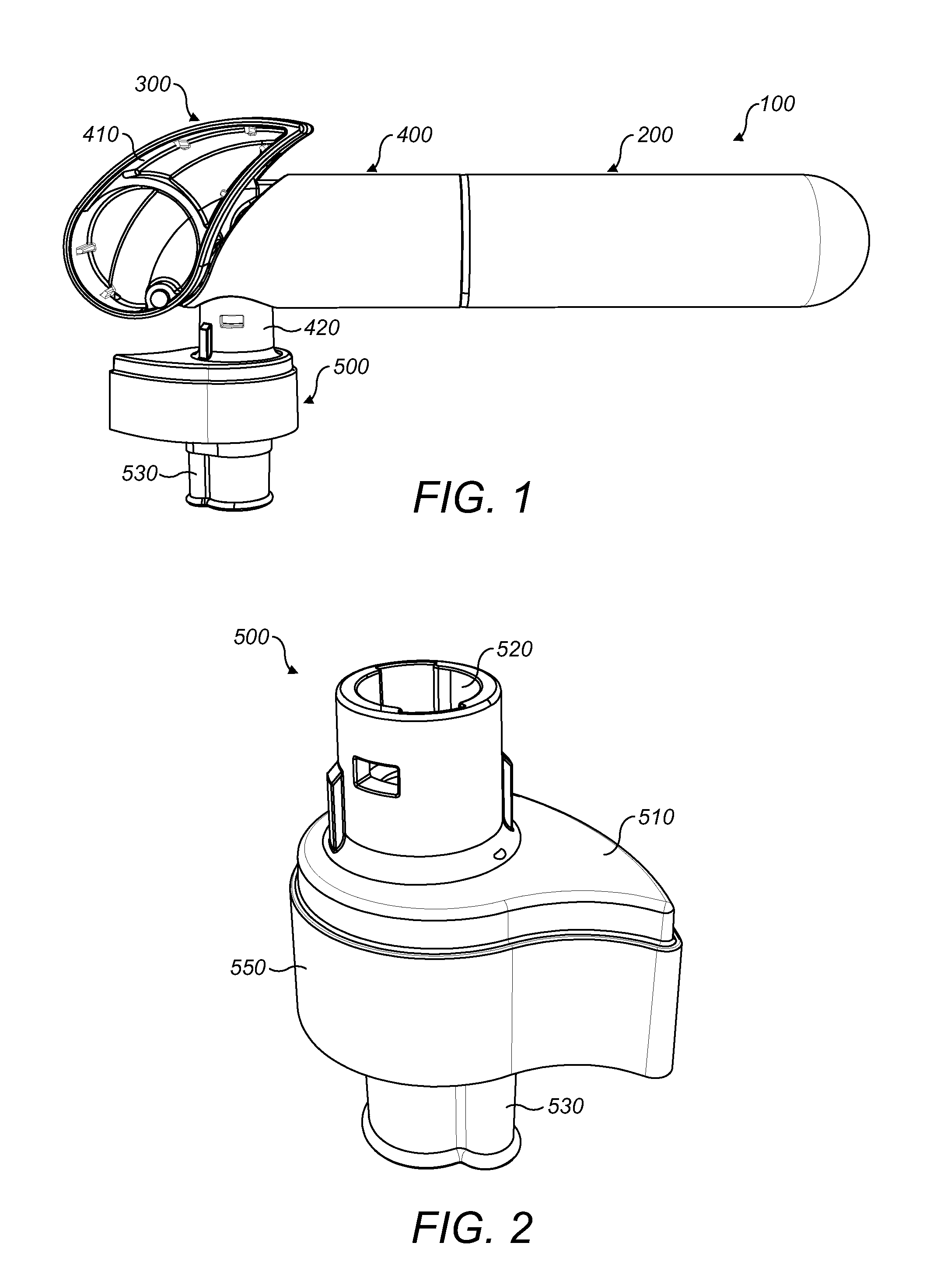
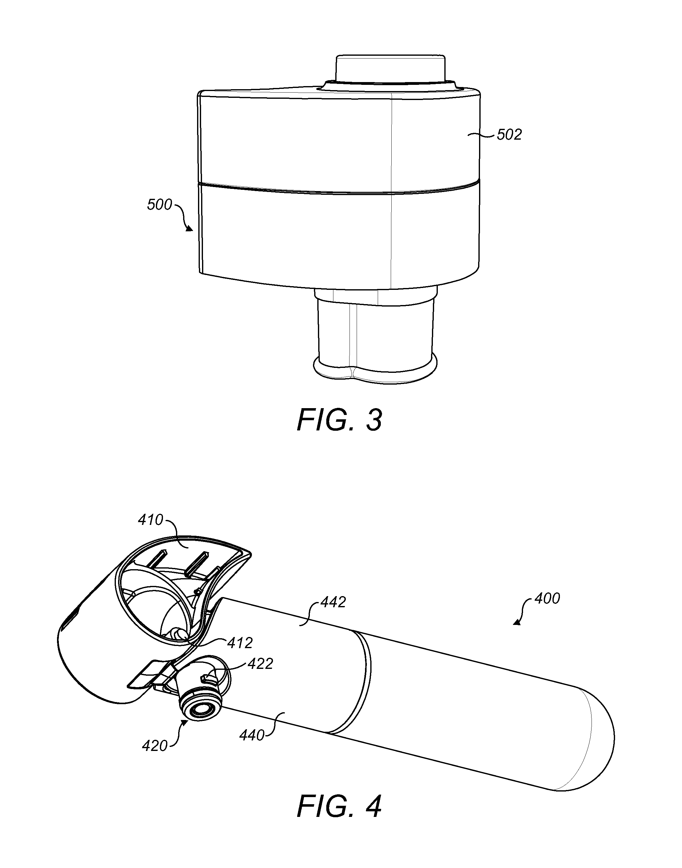
[0022]FIG. 1 shows a carbonating apparatus 100 comprising a compressed gas source 200 and a carbonating device 300. The carbonating device 300 is formed from two parts; a discharge assembly 400 and a cap assembly 500.

[0023]The compressed gas source 200 connects to the discharge assembly 400. Here the discharge assembly includes an inlet 402 that is opened and closed by a valve 404. The valve 404 is biased to be closed. When opened, gas is released from the gas source 200 into the discharge assembly 400.

[0024]The discharge assembly 400 includes a trigger 410. Activation of the trigger 410 cause the valve 404 to open and therefore releases gas from the compressed gas source 200 into the discharge assembly 400. The discharge assembly 400 includes a discharge port 420 that discharges gas from within the discharge assembly 400. A valve 430 is arranged to open and close the discharge port 420. The valve 430 is biased to close the discharge port 420.

[0025]The cap includes a sealing portion...


PUM

PropertyMeasurementUnit
Forceaaaaaaaaaa
Pressureaaaaaaaaaa

Abstract

A carbonating device for carbonating an opened vessel including an inlet valve for receiving pressurized gas, an exit valve for expelling gas into a vessel to be carbonated, a trigger for opening the inlet valve, a trigger pressure regulator arranged to close the inlet valve, a discharge assembly, and a cap assembly, the discharge assembly coupled to and de-coupled from the cap and including a port for discharging gas to the cap, the discharge port being opened and closed by a valve and a pressure regulator arranged to automatically close the discharge valve in response to a pressure level.

Description

CROSS-REFERENCE TO RELATED APPLICATIONS[0001]This application claims priority to PCT / GB2011 / 050261 filed Feb. 11, 2011, which claims priority to GB1002305.9 filed Feb. 11, 2010, the entirety of both of which are incorporated by reference herein.TECHNICAL FIELD AND BACKGROUND OF THE INVENTION[0002]This invention relates to a carbonating apparatus for re-carbonating beverage vessels, and in particular, although not exclusively to re-carbonating opened fizzy drink containers in order to restore or maintain the drink that remains therein. The invention also relates to a method of using a carbonating apparatus in order to restore or maintain remains of a beverage from within an opened beverage vessel.[0003]Re-carbonating apparatus are known. Such re-carbonators are particularly useful for keeping a carbonated drink fresh once a conventional carbonated drinks bottle has been opened. Carbonated drinks are known to loose freshness once a part of the contents of the beverage has been consume...

Claims


Application Information

Patent Timeline
IPC IPC(8): A23L2/54C01B32/50
CPCA23L2/54B01F3/04801B01F15/026B01F2003/04822B01F2003/049B01F23/2364B01F23/23611B01F23/237621B01F35/71805B01F23/232B01F23/236B01F23/2361
Inventor GORMLEY, DAVID MICHAELDURANT, MARCUS
Owner GOBUBL
Learn More