Method for regenerating a particulate filter for a boosted direct injection engine

a direct injection engine and particulate filter technology, applied in the direction of electrical control, couplings, fluid couplings, etc., can solve the problems of short opportunity for the injected fuel to completely fill, and the formation of particles in the engine exhaust, so as to reduce the emissions of soot, improve the engine performance, and reduce the disturbance of transient air-fuel

Active Publication Date: 2013-06-18
FORD GLOBAL TECH LLC
View PDF36 Cites 14 Cited by
  • Summary
  • Abstract
  • Description
  • Claims
  • Application Information

AI Technical Summary

Benefits of technology

[0003]Recently, direct injection gasoline engines have been shown to improve engine performance and to reduce transient air-fuel disturbances that may be caused by fuel adhering to the intake manifold and ports of an engine. However, at higher engine speeds and higher engine loads, particulates may form in engine exhaust. Under some conditions, formation of the particulates may be related to the short amount of time between when fuel is injected to the cylinder and when combustion is initiated by a spark plug. Specifically, there may be only a short opportunity for the injected fuel to completely vaporize and form a homogeneous mixture before combustion is initiated. If a homogeneous air-fuel mixture is not formed in the cylinder before combustion is initiated, pockets of stratification may form, and soot may be produced by combusting rich areas within the cylinder air-fuel mixture. Particulate filters have been proposed as one way to reduce emissions of soot.
[0004]The inventors herein have developed a method for regenerating a particulate filter without having to provide an external air supply. In particular, the inventors have developed a method for regenerating a particulate filter of a direct injection gasoline engine, comprising: increasing an overlap between an intake valve and an exhaust valve of a cylinder in response to an operating condition of a particulate filter.
[0006]The present description may provide several advantages. Specifically, the approach may improve engine emissions by allowing a cylinder to operate at stoichiometric conditions while regenerating a particulate filter. Further, the amount of excess oxygen supplied to oxidize soot held by the particulate trap may be varied so that the soot is combusted efficiently. Further still, oxygen can be supplied to a particulate filter in the exhaust system without the need of an auxiliary air pump.

Problems solved by technology

However, at higher engine speeds and higher engine loads, particulates may form in engine exhaust.
Specifically, there may be only a short opportunity for the injected fuel to completely vaporize and form a homogeneous mixture before combustion is initiated.

Method used


Image

  • Method for regenerating a particulate filter for a boosted direct injection engine
  • Method for regenerating a particulate filter for a boosted direct injection engine
  • Method for regenerating a particulate filter for a boosted direct injection engine

Examples


Embodiment Construction

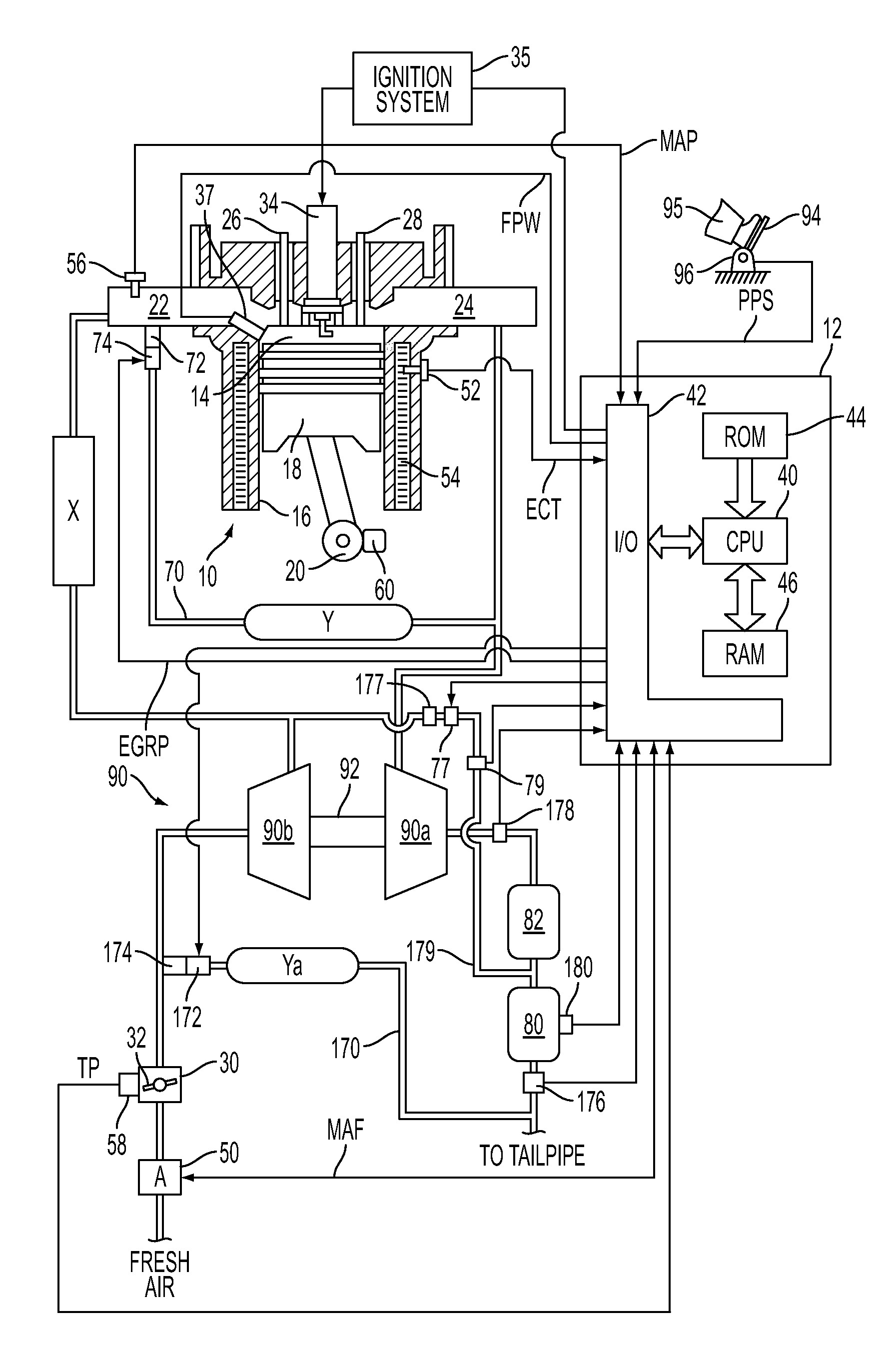
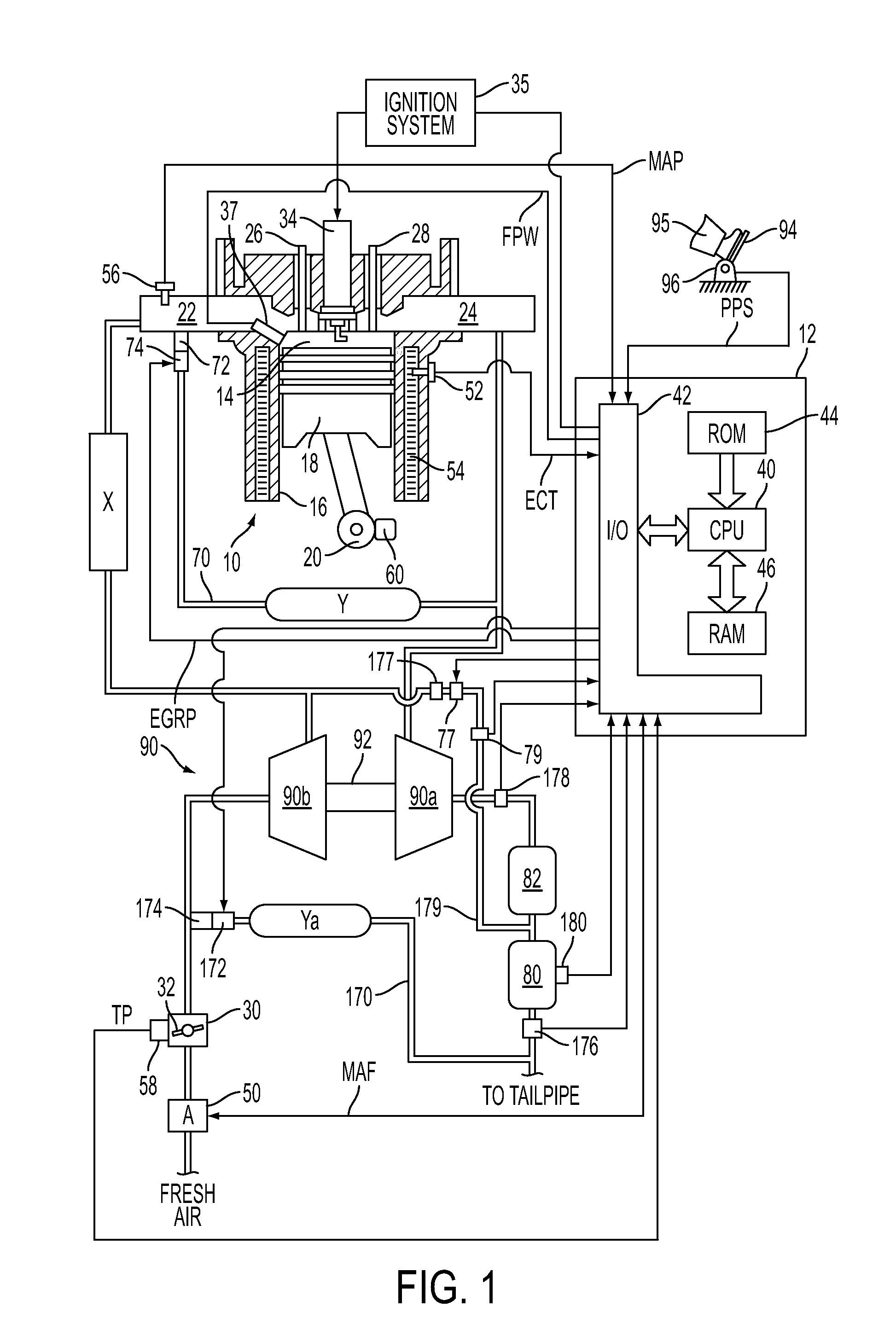
[0014]FIG. 1 shows an exemplary embodiment of a gasoline direct injection engine system generally at 10. Specifically, internal combustion engine 10 comprises a plurality of cylinders, one cylinder of which is shown in FIG. 1. Engine 10 is controlled by electronic engine controller 12. Engine 10 includes combustion chamber 14 and cylinder walls 16 with piston 18 positioned therein and connected to crankshaft 20. Combustion chamber 14 communicates with an intake manifold 22 and an exhaust manifold 24 via respective intake valve 26 and exhaust valve 28.

[0015]Intake manifold 22 communicates with throttle body 30 via throttle plate 32. In one embodiment, an electronically controlled throttle can be used. In one embodiment, the throttle is electronically controlled to periodically, or continuously, maintain a specified vacuum level in intake manifold 22. Note that throttle body 30 and throttle plate 32 may be located at a location downstream of compression device 90 in some applications....


PUM


Abstract

A method for regenerating a particulate filter is disclosed. In one example, oxygen is pumped from the intake system of a direct injection turobocharged gasoline engine through a cylinder and into the exhaust system by a compressor. In this way, regeneration of a particulate filter may be accomplished without an auxiliary air supply.

Description

CROSS-REFERENCE TO RELATED APPLICATIONS[0001]This application claims priority from U.S. Provisional Patent Application No. 61 / 246,926, entitled “SYSTEM AND METHOD FOR REGENERATING A PARTICULATE FILTER FOR A DIRECT INJECTION ENGINE”, filed Sep. 29, 2009, the disclosure of which is hereby incorporated by reference in its entirety and for all purposes.TECHNICAL FIELD[0002]The present application relates to the field of automotive emission control systems and methods.BACKGROUND AND SUMMARY[0003]Recently, direct injection gasoline engines have been shown to improve engine performance and to reduce transient air-fuel disturbances that may be caused by fuel adhering to the intake manifold and ports of an engine. However, at higher engine speeds and higher engine loads, particulates may form in engine exhaust. Under some conditions, formation of the particulates may be related to the short amount of time between when fuel is injected to the cylinder and when combustion is initiated by a spa...

Claims


Application Information

Patent Timeline
Patent Type & Authority Patents(United States)
IPC IPC(8): F01N3/22
CPCF02D41/0007F02D41/029F01N3/0233F01N3/0236F02D2041/001F01N9/002Y02T10/144Y02T10/12
Inventor KERNS, JAMES MICHAELCUNNINGHAM, RALPH WAYNERUHLAND, HELMUT HANSSPRINGER, MORITZ KLAUSLORENZ, THOMASLOUVEN, GEORGHARMSEN, JAN
Owner FORD GLOBAL TECH LLC
Why Eureka
Try Eureka