
Headlamp and vehicle infrared night vision apparatus employing the headlamp as light source

a headlamp and infrared technology, applied in the field of headlamps, can solve the problems of high price, significant increase in power consumption, and infrared camera, which captures a very small amount of far infrared radiation emitted by pedestrians, animals or the like, and achieves the effect of long service life and low power consumption

Active Publication Date: 2013-06-18
SHARP FUKUYAMA LASER CO LTD
View PDF24 Cites 13 Cited by
  • Summary
  • Abstract
  • Description
  • Claims
  • Application Information

AI Technical Summary

Benefits of technology

The present invention provides a headlamp that has lower power consumption, longer service life, and a more compact size. It can easily project visible light and near infrared light in desired patterns without the need for complex optical systems. The headlamp uses a semiconductor solid-state element as the excitation light source and includes both visible light fluorescent material and near infrared fluorescent material. This ensures that both visible and near infrared light can be emitted with a single excitation light source. Overall, the headlamp has the benefits of lower power consumption, longer service life, and compact size while providing desired light distribution patterns without complicating the optical system.

Problems solved by technology

In the automotive night vision apparatus of the passive type, the infrared camera, which captures a very small amount of far infrared radiation emitted from the pedestrian, the animal or the like, is very expensive.
However, where the bulb for the high beam projection is used as a near infrared light source, the high beam bulb is constantly turned on, disadvantageously leading to a significant increase in power consumption.
That is, the high beam bulb leads to the significant increase in the power consumption of the headlamp because the high beam bulb is turned on even during the projection of the low beam.
At the same time, the high beam bulb suffers from a shorter service life and hence a shorter bulb change cycle because the high beam bulb is constantly turned on.
Provision of the dedicated optical system inevitably increases the size of the entire infrared night vision apparatus.
Therefore, the optical system of the headlamp is disadvantageously complicated in order to project the near infrared light in a desired light distribution pattern.
Further, a strict limitation is imposed on positional relationships between the reflection mirror and the visible LED and between the reflection mirror and the near infrared LED.

Method used


Image

  • Headlamp and vehicle infrared night vision apparatus employing the headlamp as light source
  • Headlamp and vehicle infrared night vision apparatus employing the headlamp as light source
  • Headlamp and vehicle infrared night vision apparatus employing the headlamp as light source

Examples


embodiment 1

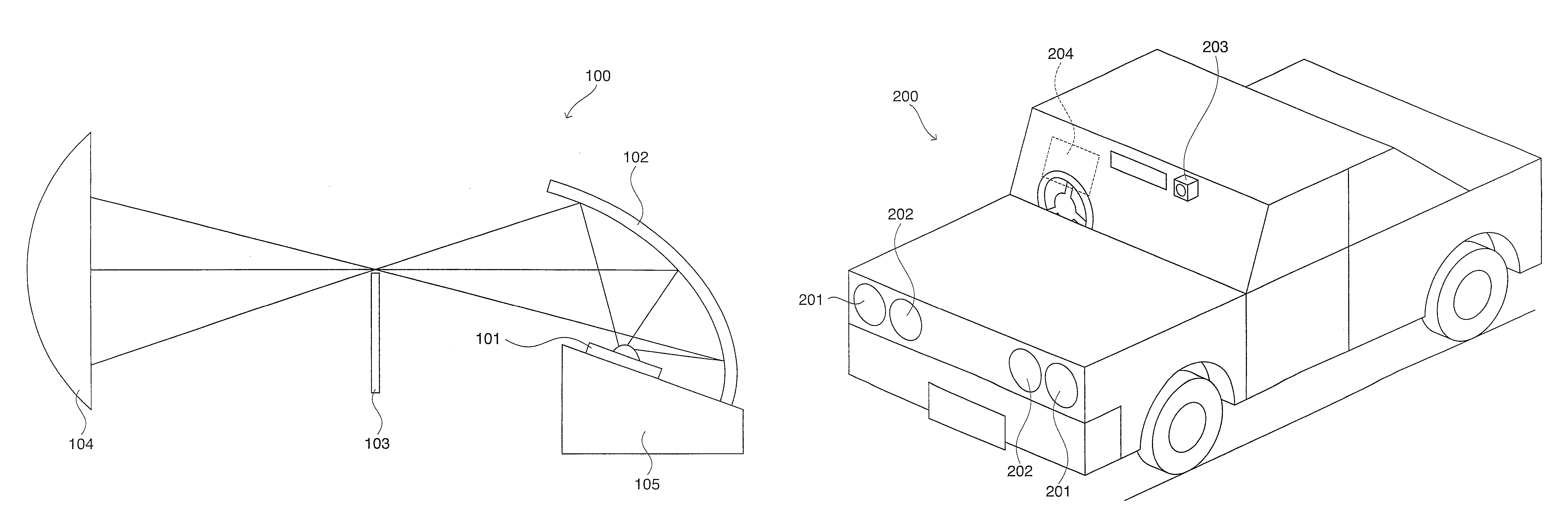
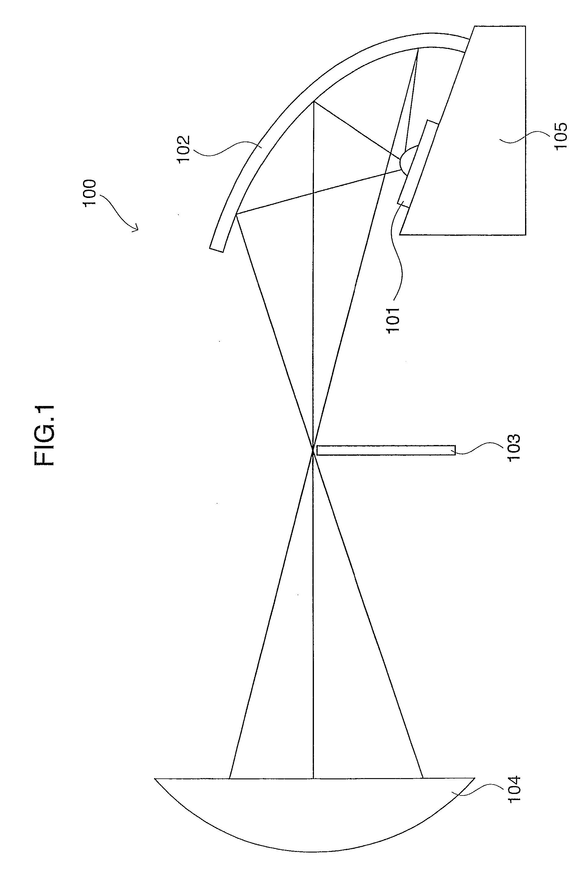
[0057]FIG. 1 is a schematic sectional view of a headlamp according to Embodiment 1. In FIG. 1, the headlamp 100 includes a light emitting portion 101, a reflection mirror 102 having a rotational ellipsoidal surface, a light blocking plate 103, and a projection lens 104. The light emitting portion 101 includes a wavelength converting member including a visible light fluorescent material and a near infrared fluorescent material, and an excitation light source of a semiconductor solid-state element. The light blocking plate 103 transmits near infrared light, and partly blocks visible light to define a cut line for a low beam. The light emitting portion 101 and the reflection mirror 102 are fixed to a unitary support member 105.

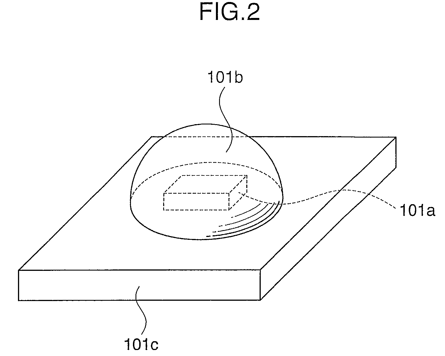
[0058]As shown in FIG. 2, the light emitting portion 101 includes an excitation light source 101a, a wavelength converting member 101b, and a ceramic package 101c on which the wavelength converting member 101b is fixed. The excitation light source 101a is a GaN l...

embodiment 2

[0084]The construction of a headlamp according to Embodiment 2 of the present invention will hereinafter be described. The headlamp of Embodiment 2 has substantially the same construction as the headlamp of Embodiment 1 described above, except that the excitation light source of the light emitting portion is a semiconductor laser element. More specifically, the light emitting portion is configured such that the wavelength converting member containing the visible light fluorescent material and the near infrared fluorescent material is disposed on a light emitting side of the semiconductor laser element from which the excitation light (laser beam) is emitted.

[0085]In Embodiment 2, the semiconductor laser element serving as the light source oscillates at a wavelength of 405 nm. The visible light fluorescent material includes two types of fluorescent materials which absorb light at a wavelength of 405 nm and respectively emit cyan light and red light (Ca-α-SiAlON:Ce3+ capable of emittin...

embodiment 3

[0090]FIG. 4 is a schematic diagram illustrating a vehicle infrared night vision apparatus 200 according to Embodiment 3. Two low beam projection headlamps 201 each having the same construction as the headlamp 100 of Embodiment 1 are disposed on right and left portions of the front face (front portion) of an automobile. High beam projection headlamps 202 each having substantially the same construction as the headlamp of Embodiment 2 except that the light blocking plate is removed are disposed laterally inward of the low beam projection headlamps 201. Further, a near infrared camera 203 is disposed on a lateral side of a rear-view mirror provided inward of a front glass. An obstacle, a pedestrian and the like detected by the near infrared camera 203 are displayed on a front glass portion 204 by a so-called head-up display method. The aforementioned silicon PIN photodiode is used as a light receiving element of the near infrared camera.

[0091]In Embodiment 3, semiconductor solid-state ...


PUM


Abstract

A headlamp is provided, which has lower power consumption, a longer service life and a more compact size and yet is capable of easily projecting visible light and near infrared light in desired light distribution patterns. The headlamp includes a wavelength converting member and an excitation light source. The wavelength converting member includes a visible light fluorescent material which is excited by excitation light emitted from the excitation light source to emit visible light, and a near infrared fluorescent material which is excited by the excitation light emitted from the excitation light source to emit near infrared light. The visible light and the excitation light are mixed together to generate white light. The excitation light source is a semiconductor solid-state element.

Description

CROSS-REFERENCE TO RELATED APPLICATIONS[0001]This application is related to Japanese patent application No. 2008-64530 filed on Mar. 13, 2008, whose priority is claimed under 35 USC §119, and the disclosure of which is incorporated by reference in its entirety.BACKGROUND OF THE INVENTION[0002]1. Field of the Invention[0003]The present invention relates to a headlamp. More specifically, the invention relates to a headlamp which is advantageously used as a light source for an infrared night vision apparatus for a motor vehicle such as an automobile.[0004]2. Description of the Related Art[0005]In recent years, a safety technique that makes it easy to visually detect pedestrians and obstacles in the dark by means of an infrared night vision apparatus has been increasingly employed for enhancement of safety in driving an automobile at night.[0006]Various types of automotive night vision apparatuses have been developed which, for example, include a so-called passive type and a so-called a...

Claims


Application Information

Patent Timeline
Patent Type & Authority Patents(United States)
IPC IPC(8): F21V9/00
CPCB60Q1/04
Inventor KISHIMOTO, KATSUHIKOKINOMOTO, JUNICHI
Owner SHARP FUKUYAMA LASER CO LTD
Learn More