Fouling and corrosion detector for burner tips in fired equipment

a burner tip and detector technology, applied in the field of combustion systems, can solve problems such as system failure, burner tip or nozzle fouling or corrosion, and process that uses fired equipmen

Active Publication Date: 2013-06-25
ROSEMOUNT INC
View PDF126 Cites 3 Cited by
  • Summary
  • Abstract
  • Description
  • Claims
  • Application Information

AI Technical Summary

Benefits of technology

[0060]The present invention also provides an advantage in that it is possible to detect developing problems in an industrial process based on significant changes in background noise, independent of the acoustic signature used to predict fouling and corrosion. For example, in moving equipment, as bearings begin to fail, the equipment generates increasing noise output. This change in noise output will alter the background noise of the detected signal, and significant changes can be analyzed to predict potential service needs of other adjacent equipment, before catastrophic failure.

Problems solved by technology

One common failure mode for processes that use fired equipment is fouling or corrosion of the burner tips or nozzles, which deliver fuel to the combustion chamber.
Such fouling or corrosion can impact fuel delivery, and can result in system failure and sometimes plant shut down.
In the process industry, unplanned plant downtime events caused by fired equipment failure can be very expensive, including lost production costs and the cost of shutdown / start up.
In addition to such costs, the events that caused the plant downtime can also result in safety issues, environmental issues, and faulty products.
In some embodiments, a fired equipment unit has multiple burner tips, making upstream detection somewhat difficult.
Specifically, as a single burner tip within a set of burner tips becomes plugged or corroded, an upstream sensor may not detect any change in fuel flow to the burner unit having multiple burner tips, because some burner tips of the burner unit may simply produce a slightly larger flame.
Alternatively, if the fuel is corrosive, a corroded burner tip may simply burn more fuel but less efficiently.
Identifying which burner tip is actually plugged or corroded may be difficult if not impossible without shutting down the system.
Another problem associated with such systems is that fouling and / or corrosion of a burner tip typically causes lower heat output.
The increased fuel flow may result in increased flame output from other, unplugged burners, thereby creating an uneven heating situation or hot spots within the system.
Uneven heating may result in decreased efficiency, decreased product quality, and various other undesirable results.
Moreover, if the burners are burn more fuel because another burner is plugged, they may produce a flame that is hotter than that for which the burner is rated, thereby exposing the burner to a temperature greater than it can withstand.
Such hot spots eventually can lead to premature failure of the tubes or separator walls.
Within the process itself, such hot spots may ruin the process.

Method used


Image

  • Fouling and corrosion detector for burner tips in fired equipment
  • Fouling and corrosion detector for burner tips in fired equipment
  • Fouling and corrosion detector for burner tips in fired equipment

Examples


Embodiment Construction

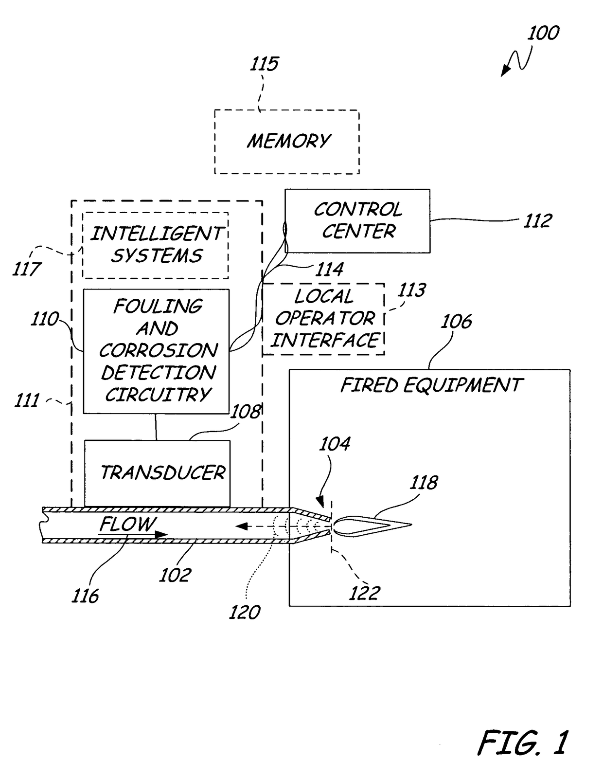
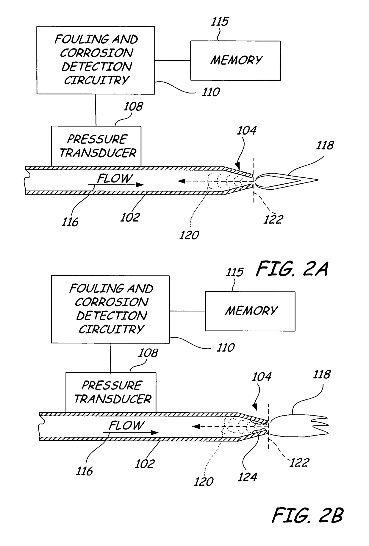
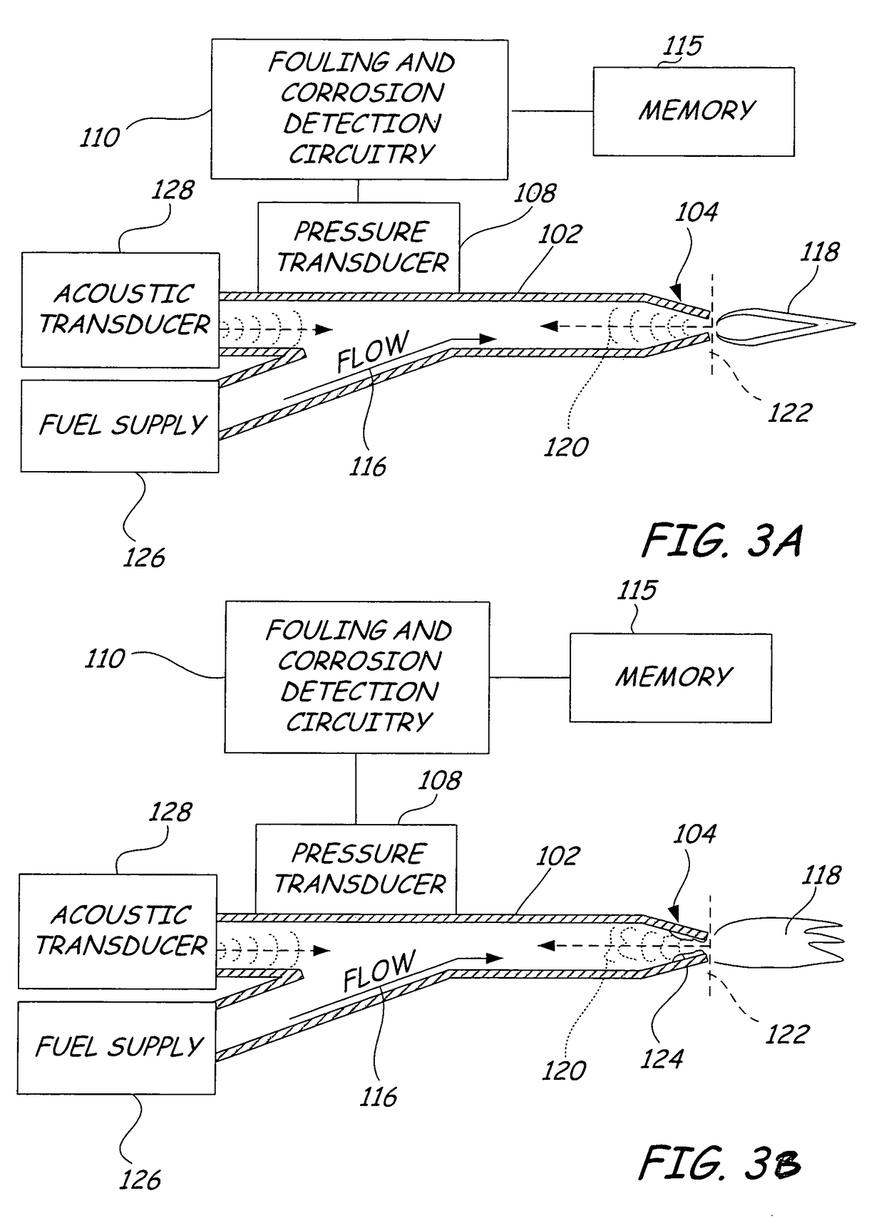
[0014]Generally, fluids flowing within a pipe or conduit produce detectable acoustic signals as the fluid contacts the walls of the pipe. Adjacent to narrowing or obstructive elements within a pipe (such as a venture tube, a burner tip, and the like), the changing inner diameter of the pipe cause acoustic reflections, which are detectable upstream from the narrowing or obstructive element. For example, as fuel flows through a burner tip, the fuel flow through the narrowing flow path causes an acoustic reflection substantially opposite to the direction of flow. Typically, this acoustic reflection can be considered as an acoustic signature, which varies with flow rate. However, this acoustic reflection or signature changes as fouling or corrosion effects the narrowing or obstructing element. Both fouling (buildup of undesirable material on the surface) or corrosion (pitting or erosion of surface material) cause a change in the profile of the obstructing or narrowing element, resulting...


PUM

PropertyMeasurementUnit
foulingaaaaaaaaaa
corrosionaaaaaaaaaa
pressureaaaaaaaaaa

Abstract

A system for predicting fouling and corrosion of a combustion system in an industrial process includes a pipe, a restrictive element, and a fouling and corrosion detector. The pipe contains a fuel. The restrictive element is coupled to the pipe and the fuel passes through the restrictive element. The fouling and corrosion detector is coupled to the pipe and is adapted to detect a characteristic signature of the restrictive element and to generate an alarm if a change in the detected signature exceeds a predetermined limit relative to a baseline signature.

Description

BACKGROUND OF THE INVENTION[0001]The present invention relate to combustion systems. More particularly, the invention relates to an apparatus for detecting fouling or corrosion in burner tips within a fired equipment system.[0002]The term “fired equipment” or “heat delivery system” refers to devices that utilize fire or flames to deliver heat to a system. Typically, fired equipment utilizes a fuel delivery system for controlled delivery of fuel to a combustion chamber or to a burner tip. As used herein, the term “fuel” may be a gas, a liquid, a flammable mixture (such as coal particles in an oil suspension), or any flammable substance that is amenable to controlled delivery through a burner tip. Examples of fired equipment include incinerators, heat exchangers, reactors, boilers, and the like. One common failure mode for processes that use fired equipment is fouling or corrosion of the burner tips or nozzles, which deliver fuel to the combustion chamber. Such fouling or corrosion ca...

Claims


Application Information

Patent Timeline
Patent Type & Authority Patents(United States)
IPC IPC(8): G01N29/036F23D14/24
CPCG01N17/00G01N17/008G01N29/11G01N29/12G01N29/4427G01N29/4481G01N2291/02872G01N2291/044G01N2291/2634
Inventor PELUSO, MARCOSELIASON, SCOTTBROWN, GREGORY C.
Owner ROSEMOUNT INC
Why Eureka
Try Eureka