

Laser hybrid welding method and laser hybrid welding torch using a zinc and/or carbon and/or aluminum-containing rod
Inactive Publication Date: 2013-06-25
FRONIUS INTERNATIONAL GMBH
View PDF31 Cites 19 Cited by
- Summary
- Abstract
- Description
- Claims
- Application Information
AI Technical Summary
Benefits of technology
This patent text describes a method for welding coated sheet metals with the goal of minimizing or eliminating the formation of inclusions caused by the evaporation of the coating. The method also aims to provide stability and tightness to the weld seam and to minimize the time and cost of preparing the sheet metals for welding. Additionally, the text discusses the use of a particular filler material in combination with a laser hybrid welding process to achieve a tight and stable weld seam without the need for post-welding finishing. The use of a zinc, carbon, or aluminum content welding wire in combination with a zinc coated sheet metal further enhances the harmonization process and the production of a tight weld seam without any finishing operations.
Problems solved by technology
Although it is pointed out that even coated workpieces can be welded together, the problems caused by the evaporation of the coating are not discussed, nor is any solution to overcome those problems suggested.
Method used
View moreImage
Smart ImageViewing Examples

Examples
example 1
Electrolytic zinc coating ZE75 / 75 according to EN 10152
Stitch seam in the lap joint:
Welding wire: SAF DUAL ZN®
vs: 3 m / min
I: 50 A
vD: 1.6 m / min
U: 12.2 V
Distance: 2 mm
PL: 3.9 kW
Focus diameter: 0.8 mm
example 2
Z 100 galvanized zinc coating: zinc layer thickness: 7.5 μm Butt seam
Welding wire: SAF DUAL ZN®
vs: 2.4 m / min
Login to View More PUM
| Property | Measurement | Unit |
|---|---|---|
| Distance | aaaaa | aaaaa |
| Distance | aaaaa | aaaaa |
| Distance | aaaaa | aaaaa |
Abstract
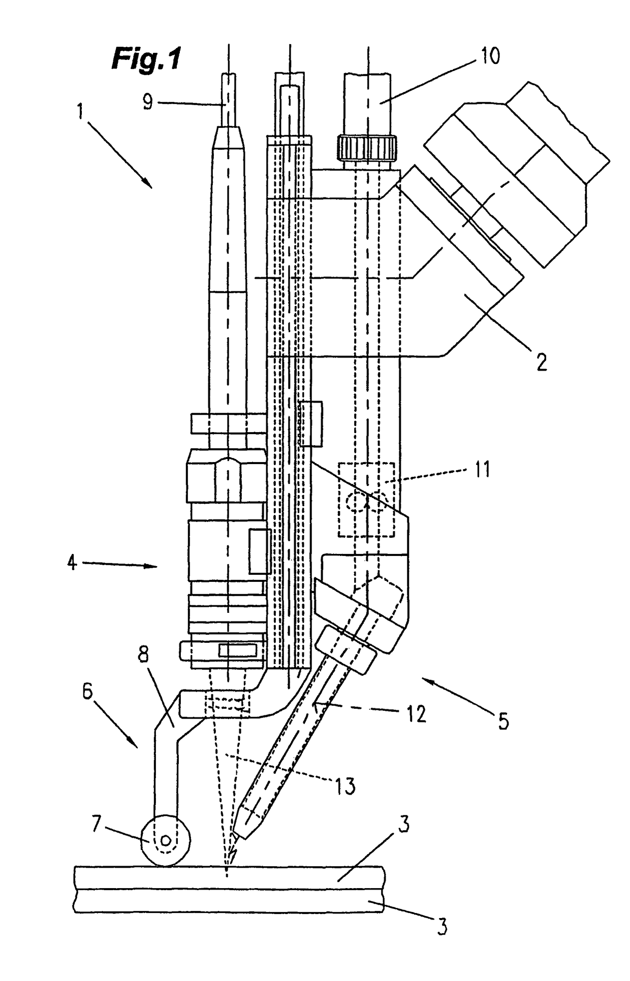
The invention relates to a method for welding coated sheet metal (3), which comprises at least one laser (13) and at least one shielded arc unit (5) and a rod feeding device (11) for a welding rod (12). The aim of the invention is to provide a method or a device of the aforementioned kind which allows fo˜ reducing or completely avoiding inclusions such as are e.g. caused by the evaporation of the coating of the metal sheet (3). For this purpose, a clamping device (6) is used for positioning the coated metal sheet (3) without substantial gaps between the individual sheets. A material having a zinc and / or carbon and / or aluminum content is used as the weld metal or welding rod (12).
Description
CROSS REFERENCE TO RELATED APPLICATIONS[0001]Applicants claim priority under 35 U.S.C. §119 of Austrian Application No. A802 / 2004 filed May 10, 2004. Applicants also claim priority under 35 U.S.C. §365 of PCT / AT2005 / 000156 filed May 9, 2005. The international application under PCT article 21(2) was not published in EnglishBACKGROUND OF THE INVENTION[0002]1. Field of the Invention[0003]The invention relates to a method for welding coated sheet metals using a laser hybrid welding process, wherein at least one laser process and one shielding gas welding process are carried out, with a filler material being supplied to the welding site via the shielding gas welding process.[0004]Moreover, the invention relates to a method for starting a laser hybrid welding process for welding coated sheet metals, wherein at least one laser process and one shielding gas welding process are carried out with the laser process preceding the shielding gas welding process, and the shielding gas welding proce...
Claims
Login to View More Application Information
Patent Timeline
 IPC IPC(8): B23K26/24B23K9/173B23K26/02B23K26/14B23K26/32B23K26/42B23K28/02B23K35/02B23K35/30
CPCB23K9/173B23K26/023B23K26/246B23K26/3206B23K26/3293B23K26/421B23K26/1429B23K35/0266B23K35/3053B23K28/02B23K2201/18B23K2201/34B23K2203/04B23K26/037B23K26/32B23K26/244B23K26/60B23K35/28B23K35/282B23K35/286B23K35/0255B23K35/0261B23K35/24B23K26/348B23K2101/18B23K2101/34B23K2103/04B23K2103/08B23K2103/50
InventorMIESSBACHER, GERHARDRUHRNOSSL, MANFRED
OwnerFRONIUS INTERNATIONAL GMBH