Organic electroluminescent device

an electroluminescent device and organ technology, applied in the field of organic electroluminescence devices, can solve problems such as efficiency improvement, and achieve the effects of improving efficiency and lifetime of fluorescent devices, and improving efficiency of fluorescent devices

Active Publication Date: 2013-07-02
IDEMITSU KOSAN CO LTD
View PDF24 Cites 33 Cited by
  • Summary
  • Abstract
  • Description
  • Claims
  • Application Information

AI Technical Summary

Benefits of technology

[0072]As explained hereinbelow, if a host and a dopant are combined such that the relationship Ah<Ad is satisfied, the advantageous effects of the blocking layer provided within the electron-transporting region are exhibited significantly, whereby improvement in efficiency due to the TTF phenomenon can be attained. An explanation is made on two different cases (1-1) and (1-2) given below. Generally, an organic material has a broadening of a LUMO level in a range which is larger by about 0.2 eV than the affinity level measured.
[0073]FIG. 3A is an energy band diagram showing this case. The dot line shown in the emitting layer indicates the energy level of a dopant. As shown in FIG. 3A, if the difference between Ad and Ah is smaller than 0.2 eV, the LUMO level of a dopant is included in the range of the broadening of LUMO level of a host. Therefore, electrons carried within the emitting layer are hardly trapped by a dopant. That is, this dopant hardly exhibits electron-trapping properties. In addition, the dopant of the invention is a dopant which has a wide gap which gives fluorescent emission of which the main peak wavelength is 550 nm or less. Therefore, if the relationship Ah<Ad is satisfied, since the difference between Ad and Ah is about 0.2 eV, the difference between the ionization potential of a host and the ionization potential of a dopant is decreased. As a result, a dopant does not tend to show significant hole-trapping properties.
[0074]That is, the dopant of this case does not exhibit significant trapping properties for both electrons and holes. In this case, as the slant-line portion of the emitting layer in FIG. 3A, electron-hole recombination occurs mainly on a host molecule in a broad range of the emitting layer, and 25% of singlet excitons and 75% of triplet excitons are formed mainly on a host molecule. The energy of singlet excitons which are generated on a host transfers to a dopant by the Forster energy transfer, and contributes to fluorescence emission of dopant molecules. The transfer direction of the energy of triplet excitons depends on the triplet energy relationship of a host and a dopant. If the relationship satisfies ETh>ETd, triplet excitons generated in a host transfer to a dopant which exists in the vicinity by the Dexter energy transfer. In a fluorescent device, the concentration of a dopant in the emitting layer is normally as low as several to 20 wt %. Therefore, triplet excitons which have transferred to the dopant collide with each other less frequently, resulting in a less possibility of occurrence of the TTF phenomenon. On the other hand, if the relationship ETh<ETd is satisfied, as the invention, since triplet excitons exist on host molecules, frequency of collision increases, and as a result, the TTF phenomenon easily occurs efficiently.
[0075]In the invention, a blocking layer is provided adjacent to the emitting layer. Since the triplet energy ETb of the blocking layer is larger than the triplet energy ETh of the host, diffusion of triplet excitons to the electron-transporting region can be effectively prevented, whereby the TTF phenomenon can be induced efficiently within the emitting layer.(1-2) When Difference Between Ad and Ah is Larger than 0.2 eV
[0076]The energy band in this state is shown in FIG. 3B.
[0077]The difference in affinity between a dopant and a host is increased, and the LUMO level of a dopant exists at a position further higher than the LUMO level range of a host. Therefore, a dopant tends to exhibit significant electron-trapping properties. Electrons trapped by a dopant recombine after holes move from a host to a dopant. That is, unlike the condition shown in FIG. 3A, electron-hole pairs recombine not only on host molecules but also on dopant molecules. As a result, triplet excitons are generated not only on host molecules but also directly on dopant molecules. Under such circumstances, if the relationship ETh<ETd is satisfied as the invention, triplet excitons which are generated directly on a dopant are gathered on a host by the Dexter energy transfer. As a result, the TTF phenomenon occurs efficiently.

Problems solved by technology

In a phosphorescent device, efficient confinement of triplet excitons within an emitting layer does not necessarily result in improvement in efficiency.

Method used


Image

  • Organic electroluminescent device
  • Organic electroluminescent device
  • Organic electroluminescent device

Examples


example 1

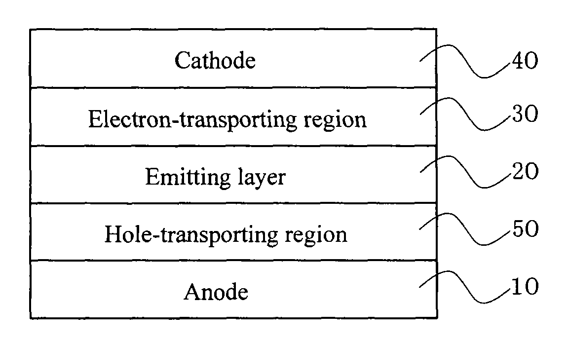
[0290]HI1, HT1, BH1:BD1(co-deposition), TB1 and ET1 were sequentially deposited on a substrate on which a 130 nm thick ITO film was formed to obtain a device with the following constitution. The figures in parentheses represent a thickness (unit: nm).

[0291]ITO(130) / HI1(50) / HT1(45) / BH1:BD1(25;5 wt %) / TB1(5) / ET1(20) / LiF(1) / Al(80)

example 2

[0296]A device with the following constitution was obtained in the same manner as in Example 1, except that the film thickness of BH1:BD1 was changed to 20 nm, and the film thickness of TB1 was changed to 10 nm.

[0297]ITO(130) / HI1(50) / HT1(45) / BH1:BD1(20;5 wt %) / TB1(10) / ET1(20) / LiF(1) / Al(80)

example 3

[0298]A device with the following constitution was obtained in the same manner as in Example 1, except that HT2 was used instead of HT1.

[0299]ITO(130) / HI1(50) / HT2(45) / BH1:BD1(25;5 wt %) / TB1(5) / ET1(20) / LiF(1) / Al(80)


PUM

PropertyMeasurementUnit
peak wavelengthaaaaaaaaaa
current efficiencyaaaaaaaaaa
internal quantum efficiencyaaaaaaaaaa

Abstract

An organic electroluminescence device including at least an anode, an emitting layer, an electron-transporting region and a cathode in sequential order, wherein the emitting layer contains a host and a dopant which gives fluorescent emission of which the main peak wavelength is 550 nm or less; the affinity Ad of the dopant is equal to or larger than the affinity Ah of the host; the triplet energy ETd of the dopant is larger than the triplet energy ETh of the host; and a blocking layer is provided within the electron-transporting region such that it is adjacent to the emitting layer, and the triplet energy ETb of the blocking layer is larger than ETh.

Description

TECHNICAL FIELD[0001]The invention relates to an organic electroluminescence (EL) device, particularly, to a highly efficient organic EL device.BACKGROUND ART[0002]An organic EL device can be classified into two types, i.e. a fluorescent EL device and a phosphorescent EL device according to its emission principle. When a voltage is applied to an organic EL device, holes are injected from an anode, and electrons are injected from a cathode, and holes and electrons recombine in an emitting layer to form excitons. According to the electron spin statistics theory, singlet excitons and triplet excitons are formed at an amount ratio of 25%:75%. In a fluorescent EL device which uses emission caused by singlet excitons, the limited value of the internal quantum efficiency is believed to be 25%. Technology for prolonging the lifetime of a fluorescent EL device utilizing a fluorescent material has been recently improved. This technology is being applied to a full-color display of portable pho...

Claims


Application Information

Patent Timeline
Patent Type & Authority Patents(United States)
IPC IPC(8): H01L51/52
CPCB82Y10/00H01L51/5016H01L51/5096C09B57/00C09B57/001C09B1/00H01L51/5028H01L51/0048H01L51/0059H01L51/0072H01L51/0073H01L51/5036H10K85/221H10K85/631H10K85/6574H10K85/6572H10K50/125H10K50/18H10K50/11H10K2101/10H10K50/121
Inventor KUMA, HITOSHIKAWAMURA, YUICHIROJINDE, YUKITOSHIOGIWARA, TOSHINARIHOSOKAWA, CHISHIO
Owner IDEMITSU KOSAN CO LTD
Why Eureka
Try Eureka