Starter for internal combustion engine

a technology for starting engines and internal combustion engines, which is applied in the direction of engine starters, couplings, machines/engines, etc., can solve the problems of excessive deformation of sealing parts, hardly allowing lubricant to leak from the mounted portion of the engine-side power transmission mechanism, and disconnection between the engine output shaft and the electric motor, so as to enhance the sealing performance of the power transmission mechanism and high coupling strength

Inactive Publication Date: 2013-07-09
TOYOTA JIDOSHA KK
View PDF10 Cites 2 Cited by
  • Summary
  • Abstract
  • Description
  • Claims
  • Application Information

AI Technical Summary

Benefits of technology

[0011]The present invention provides a starter for an internal combustion engine, which maintains a high coupling strength between the engine-side power transmission member and the engine output shaft, while enhancing the sealing performance of the power transmission mechanism.
[0013]According to the aspect, the overall contact surface area between the engine output shaft and the engine-side power transmission member is smaller relative to the case without the recessed portion, and accordingly, the pressure applied to the contact surface is higher. This enhances the sealing performance of the contact portion between the engine output shaft and the engine-side power transmission member, and therefore, enhances the sealing performance of the power transmission mechanism. Moreover, the engine-side power transmission member is fastened to the engine output shaft with no sealing member interposed between these components. This structure helps maintain the coupling strength between the engine-side power transmission member and the engine output shaft at a high level.
[0015]The groove extending in a spiral pattern may be a single groove extending in a fashion similar to a record groove. This allows the groove to be easily formed by the cutting process.
[0016]The aforementioned recessed portion may be formed into plural grooves extending about an axis of the engine output shaft. The plural grooves may be coaxial grooves. This allows the grooves to be easily formed by the cutting process.
[0018]According to this construction, when the engine-side power transmission member is fastened to the engine output shaft, protruding edges of the contact surface having a groove are subjected to plastic deformation, thereby increasing a degree of tight contact between the respective contact surfaces in the contact portion between the engine output shaft and the engine-side power transmission member. Thus, the sealing performance improves at the aforementioned contact portion. Accordingly, the sealing performance of the power transmission mechanism improves to a desired level.
[0019]The groove may be formed across the entire contact surface. According to this construction, prior to when the engine-side power transmission member is fastened to the engine output shaft, no plane contact exists between the engine output shaft and the engine-side power transmission member. Therefore, when the engine-side power transmission member is fastened to the engine output shaft, a relatively lower surface pressure suffices to achieve plastic deformation of the protruding edges of the contact surface having the groove, compared to the construction, in which a groove is formed only on a part of the contact surface. This increases the degree of tight contact between the respective contact surfaces to a desired level.

Problems solved by technology

This results in disconnection between the engine output shaft and the electric motor.
Therefore, this structure hardly allows lubricant to leak from the mounted portion of the engine-side power transmission mechanism, that is, between the engine output shaft and the engine-side power transmission member.
Therefore, applying the aforementioned sealing treatment causes the sealing member to excessively deform as the engine-side power transmission member is fastened to the engine output shaft.
This does not ensure sealing performance high enough for the mounted portion of the engine-side power transmission mechanism.

Method used


Image

  • Starter for internal combustion engine
  • Starter for internal combustion engine
  • Starter for internal combustion engine

Examples


Embodiment Construction

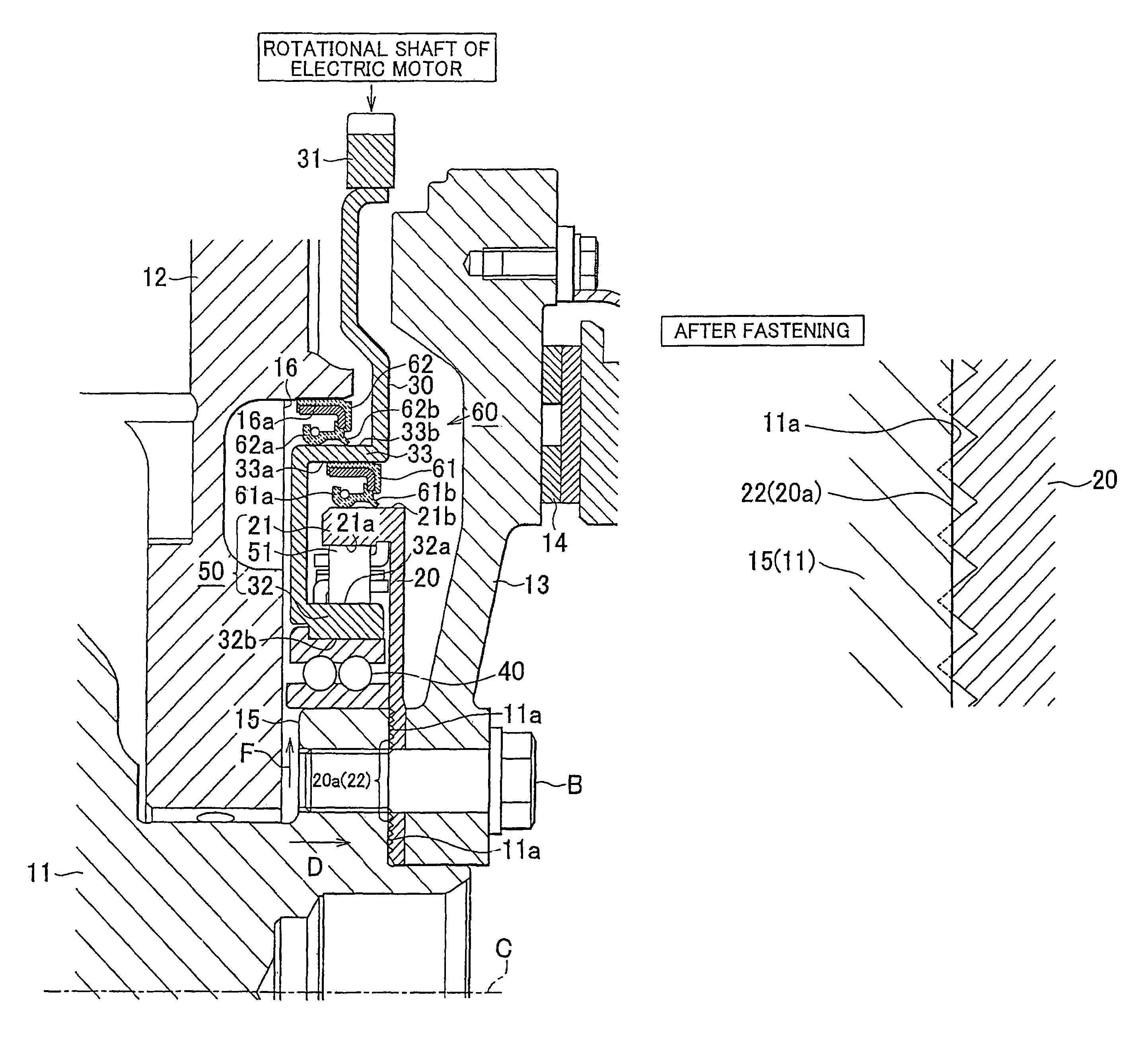
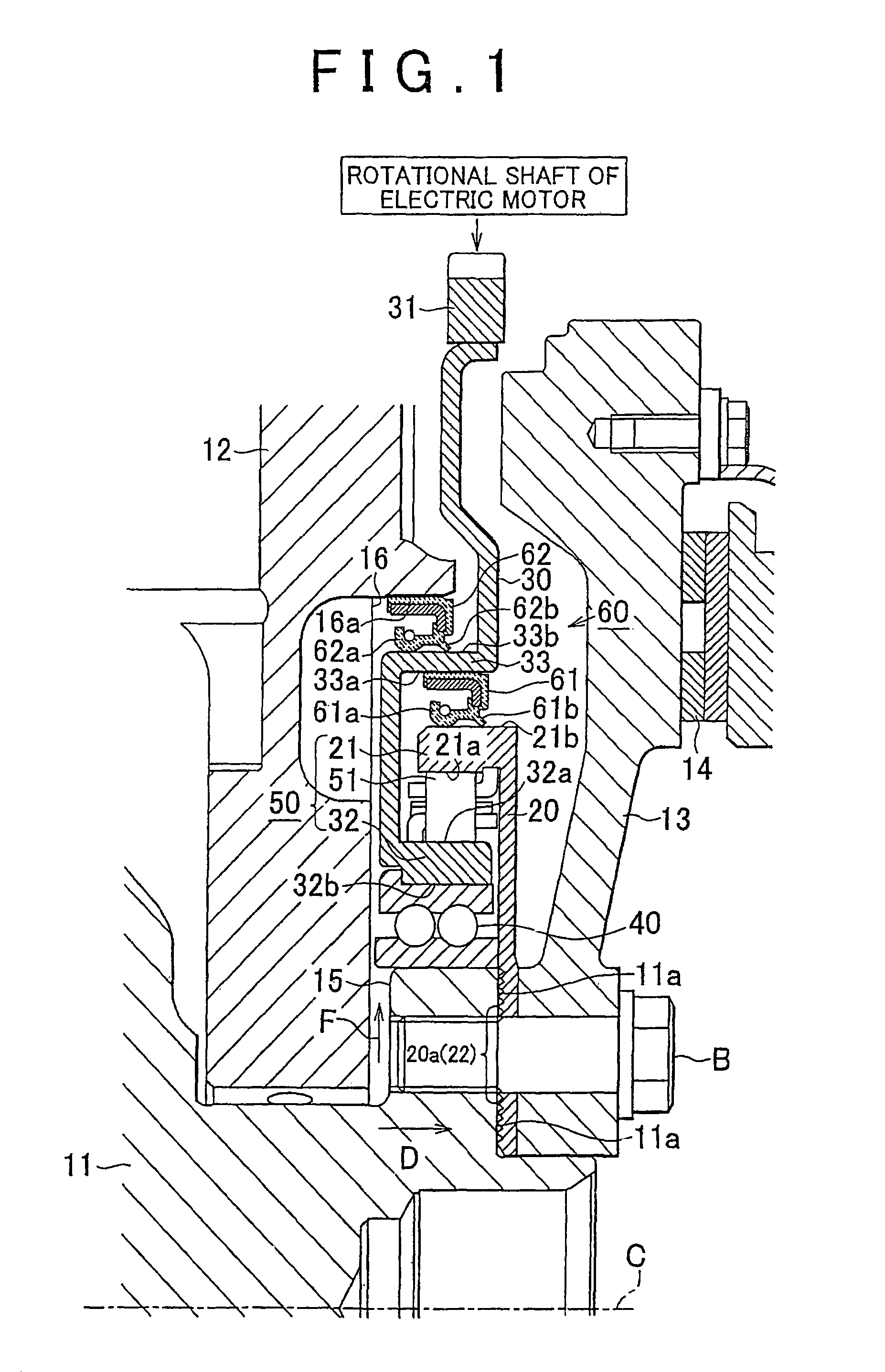
[0028]The following describes a starter for an internal combustion engine according to one embodiment of the invention. FIG. 1 shows a sectional structure of a power transmission mechanism and its surrounding area in the starter for an internal combustion engine according to the embodiment of the invention.

[0029]FIG. 1 only illustrates one side (upper side) of the power transmission mechanism with respect to the axis C of the crankshaft 11, which is output shaft of the internal combustion engine. In addition, FIG. 1 solely shows cross sections of components other than the crankshaft 11, a cylinder block 12, and a bolt B.

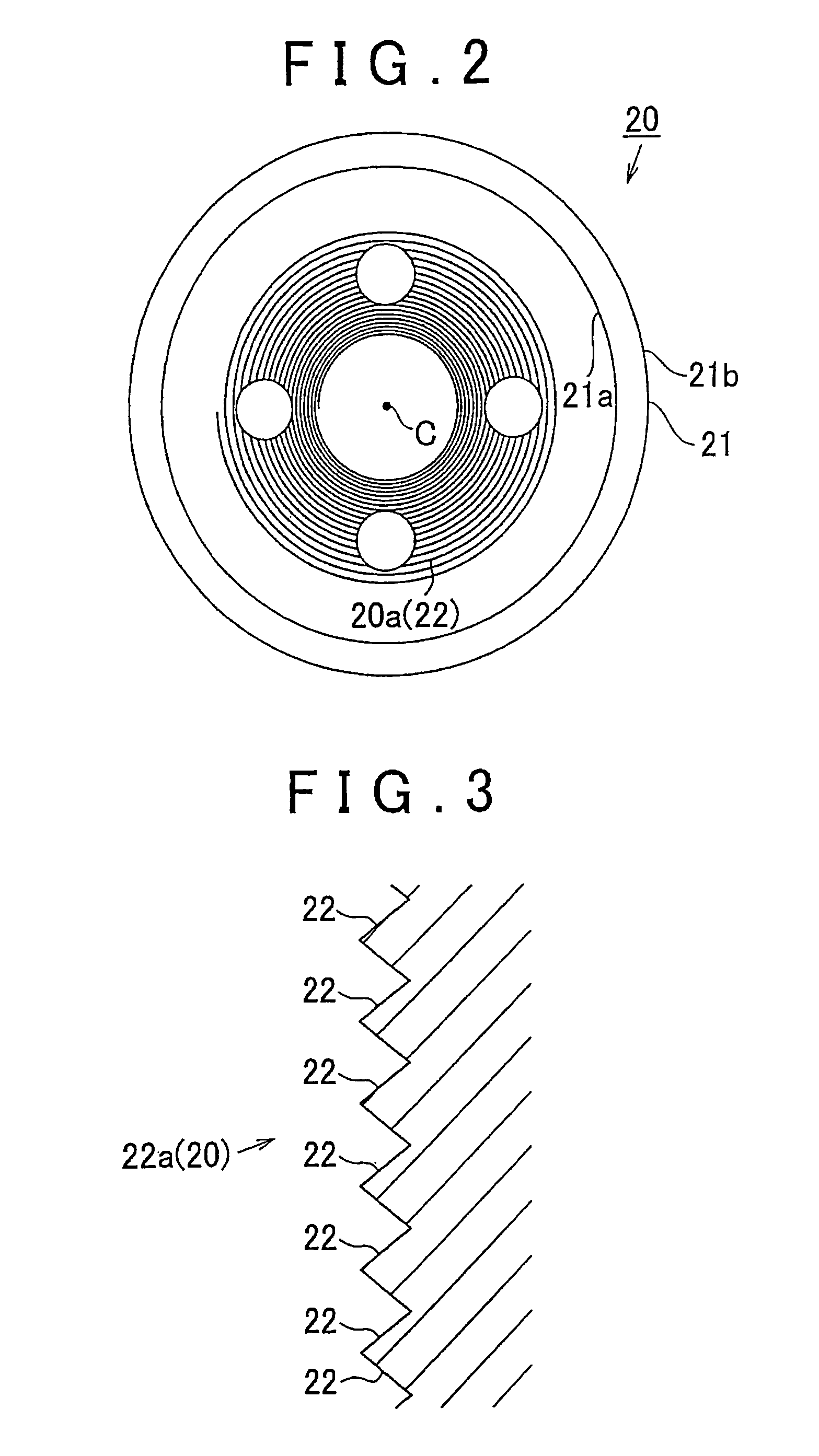
[0030]As shown in FIG. 1, the crankshaft 11 is rotatably supported between the cylinder block 12 and a ladder beam (not shown) in the internal combustion engine. A flywheel 13, an outer race plate 20, and a ring gear 30 are mounted on one end of the crankshaft 11.

[0031]The flywheel 13 is formed into an approximately disc shape having a circular opening at the center....


PUM


Abstract

A starter for an internal combustion engine includes a power transmission mechanism. The power transmission mechanism has an outer race plate fastened to a crankshaft, and a ring gear coupled to a rotational shaft of an electric motor for starting the engine. The power transmission mechanism further has a one-way clutch for permitting torque transmission only from the ring gear to the outer race plate, and two sealing members. Lubricant is supplied from the cylinder block to the interior of the power transmission mechanism for lubricating the power transmission mechanism. The outer race plate has a groove on its contact surface of a contact portion between the crankshaft and the outer race plate. The groove extends in the entire circumferential direction of the crankshaft. This maintains the coupling strength between the outer race plate and the crankshaft, while enhancing the sealing performance of the power transmission mechanism.

Description

BACKGROUND OF THE INVENTION[0001]1. Field of the Invention[0002]The present invention relates to a starter for an internal combustion engine having an electric motor that is driven to compulsory rotate an output shaft of the engine and start the engine.[0003]2. Description of the Related Art[0004]Generally, a starter for a vehicle internal combustion engine has a power transmission mechanism for transmitting the driving force of the electric starter motor to the engine output shaft such as a crankshaft. A typical structure of such power transmission mechanism is described as follows (See JP-A-2004-169668).[0005]The power transmission mechanism includes an engine-side power transmission member, an electric-motor-side power transmission member, and a one-way clutch. The engine-side power transmission member is fastened to the engine output shaft with bolts and rotates with the engine output shaft. The electric-motor-side power transmission member is provided rotatably relative to the ...

Claims


Application Information

Patent Timeline
Patent Type & Authority Patents(United States)
IPC IPC(8): F02N15/06
CPCF02N15/022F16D1/076F16D41/06F16D1/072F02N11/00F02N15/023F02N2250/08Y10T74/13Y10T74/134F02N15/00F02N15/02
Inventor SHIBA, TOSHIMITSUASADA, TOSHIAKIISHIKAWA, MAKOTOSUZUKI, TOMOAKISAKAI, KAZUHITO
Owner TOYOTA JIDOSHA KK
Why Eureka
Try Eureka