Lubricant compound for a magnetic disk, magnetic disk, and method of manufacturing the same

a technology of magnetic disks and lubricants, which is applied in the field of lubricant compounds for magnetic disks, magnetic disks, and methods of manufacturing the same, can solve the problems of reducing the thermal stability of recorded signals, affecting the increase of the recording density of magnetic disks, and affecting the recording quality of recorded signals, etc., to achieve excellent durability, reduce magnetic spacing, and high reliability

Inactive Publication Date: 2013-07-23
WESTERN DIGITAL TECH INC
View PDF13 Cites 74 Cited by
  • Summary
  • Abstract
  • Description
  • Claims
  • Application Information

AI Technical Summary

Benefits of technology

[0057]According to this invention, it is possible to provide a lubricant compound for a magnetic disk that can realize a further reduction in magnetic spacing, that is excellent in durability, particularly in LUL durability and alumina resistance, and that has high reliability even with the low flying height of a magnetic head following the rapid increase in recording density in recent years and with the very strict requirement for environmental resistance following the diversification of applications, and further to provide a magnetic disk using such a lubricant compound and a method of manufacturing such a magnetic disk.

Problems solved by technology

However, in the case of conventionally commercialized magnetic disks of the in-plane magnetic recording type (also called the longitudinal magnetic recording type or the horizontal magnetic recording type), as a result of the reduction in size of magnetic crystal grains, there has been the occurrence of a thermal fluctuation phenomenon where the thermal stability of recorded signals is degraded due to superparamagnetism and where the recorded signals are lost.
This has been an impeding factor for the increase in recording density of the magnetic disks.

Method used


Image

  • Lubricant compound for a magnetic disk, magnetic disk, and method of manufacturing the same
  • Lubricant compound for a magnetic disk, magnetic disk, and method of manufacturing the same
  • Lubricant compound for a magnetic disk, magnetic disk, and method of manufacturing the same

Examples


example 1

[0100]A magnetic disk of Example 1 has an adhesive layer, a soft magnetic layer, a first underlayer, a second underlayer, a magnetic layer, a carbon-based protective layer, and a lubricating layer which are formed in this order over a substrate.

[0101](Manufacture of Lubricant)

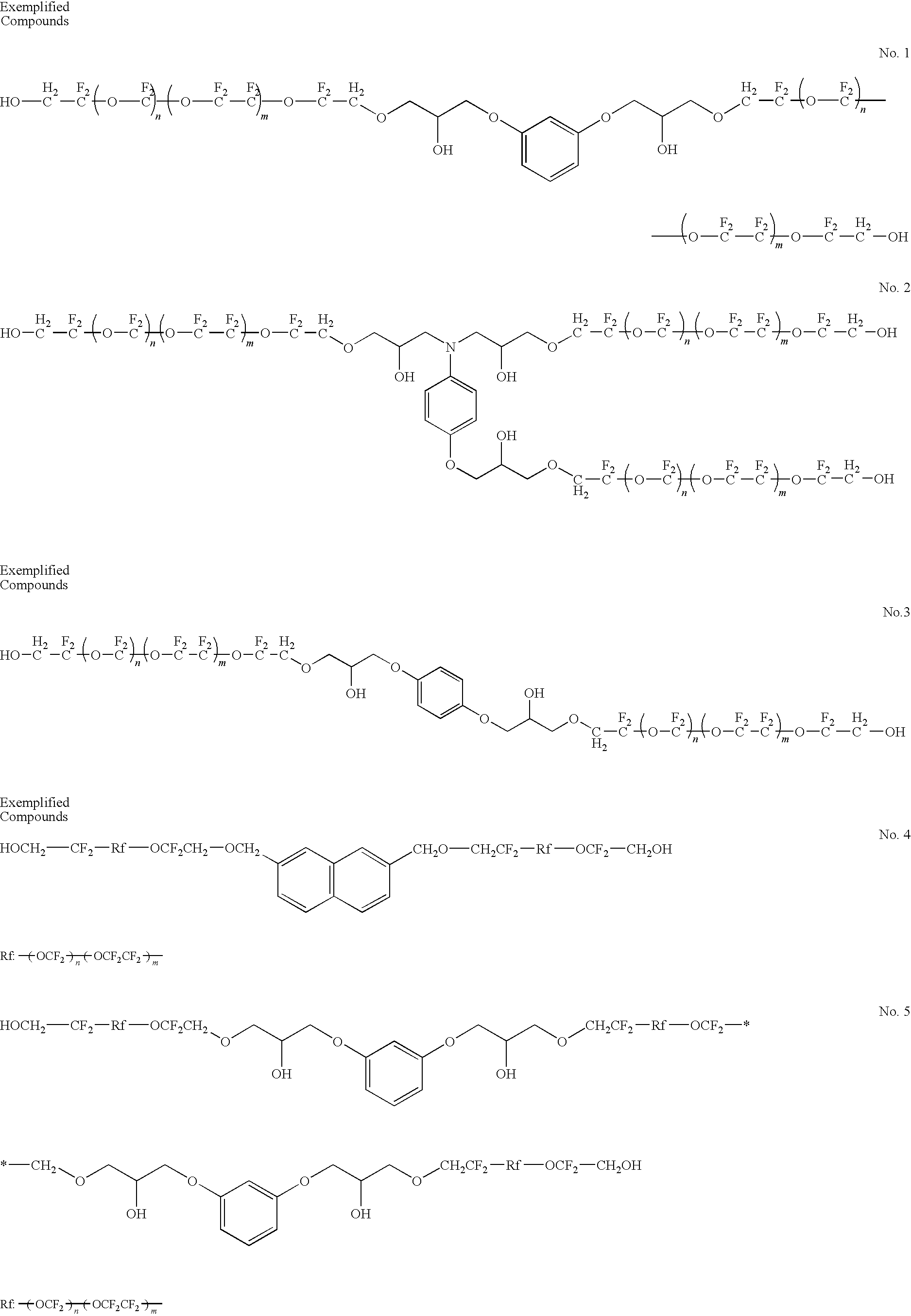
[0102]The above-exemplified lubricant compound No. 1 was manufactured according to the above synthetic scheme in the following manner.

[0103]The lubricant compound was manufactured by reacting, under an alkaline condition (NaOH), a perfluoropolyether compound having a perfluoropolyether main chain in a molecule thereof and having hydroxyl groups at both ends in the molecule (see the above synthetic scheme) with resorcinol diglycidyl ether.

[0104]A lubricant comprising the compound thus obtained was properly subjected to molecular weight fractionation by the supercritical fluid extraction method.

[0105](Manufacture of Magnetic Disk)

[0106]A 2.5-inch glass disk (outer diameter: 65 mm, inner diameter: 20 mm, disk thic...

example 2

[0125]In the same manner as in Example 1, an adhesive layer, a soft magnetic layer, a first underlayer, a second underlayer, a magnetic layer, and a carbon-based protective layer were formed and, further, a lubricating layer was formed on the protective layer by the use of the same lubricant as that in Example 1. After forming the lubricating layer, a magnetic disk was subjected to a heat treatment at 130° C. for 90 minutes and further subjected to ultraviolet irradiation. This ultraviolet irradiation was carried out for an irradiation time of 20 seconds or less by the use of an ultraviolet lamp with wavelength 185 nm: wavelength 254 nm=2:8 by the light intensity ratio. The thickness of the lubricating layer was measured by a Fourier transform infrared spectrophotometer (FTIR) and it was 12 Å. The lubricating layer coverage was 80% or more and thus was excellent. In this manner, the magnetic disk of Example 2 was obtained.

[0126]Then, a LUL durability test was performed for the magne...

example 3

Manufacture of Lubricant

[0127]The above-exemplified lubricant compound No. 2 was manufactured according to the above synthetic scheme in the following manner.

[0128]The lubricant compound was manufactured by reacting, under an alkaline condition (NaOH), a perfluoropolyether compound having a perfluoropolyether main chain in a molecule thereof and having hydroxyl groups at both ends in the molecule (see the above synthetic scheme) with the above-mentioned compound having epoxy groups and an aromatic group.

[0129]A lubricant comprising the compound thus obtained was properly subjected to molecular weight fractionation by the supercritical fluid extraction method.

[0130]An adhesive layer, a soft magnetic layer, a first underlayer, a second underlayer, a magnetic layer, and a carbon-based protective layer were formed in the same manner as in Example 1.

[0131]Then, a lubricating layer was formed in the following manner. There was prepared a solution in which the lubricant (Mn measured by the...


PUM

PropertyMeasurementUnit
flying heightaaaaaaaaaa
Raaaaaaaaaaa
Raaaaaaaaaaa

Abstract

In a magnetic disk that has at least a magnetic layer, a carbon-based protective layer, and a lubricating layer formed in this order over a substrate, the lubricating layer contains a lubricant compound including a compound which has a perfluoropolyether main chain in a structure thereof, an aromatic group located at a position except each end of a molecule thereof, and a polar group at each end of the molecule.

Description

[0001]This application is based upon and claims the benefit of priority from Japanese Patent Application No. 2009-080430, filed on Mar. 27, 2009, and Japanese Patent Application No. 2010-067387, filed on Mar. 24, 2010, the disclosures of which are incorporated herein in their entirety by reference.TECHNICAL FIELD[0002]This invention relates to a magnetic disk adapted to be mounted in a magnetic disk device such as a hard disk drive (hereinafter abbreviated as a HDD) and to a method of manufacturing the same and further relates to a lubricant compound for a magnetic disk.BACKGROUND ART[0003]Various information recording techniques have been developed following the increase in volume of information processing in recent years. Particularly, the areal recording density of HDDs using the magnetic recording technique has been increasing at an annual rate of about 100%. Recently, the information recording capacity exceeding 250 GB has been required per 2.5-inch magnetic disk adapted for us...

Claims


Application Information

Patent Timeline
Patent Type & Authority Patents(United States)
IPC IPC(8): G11B5/66
CPCG11B5/725G11B5/8408G11B5/7257
Inventor ITOH, KAEHAMAKUBO, KATSUSHISHIMOKAWA, KOICHI
Owner WESTERN DIGITAL TECH INC
Why Eureka
Try Eureka