Channel impulse response (CIR)-based and secondary synchronization channel (SSC)-based (frequency tracking loop (FTL)/time tracking loop (TTL)/channel estimation

a synchronization channel and impulse response technology, applied in the field of wireless communication systems, can solve the problems of similar performance and essentially the same overall complexity, frequency errors on the ue side, and frequency clocks in the ue may not be as accurate as the transmitting ap's, so as to achieve enhanced frequency tracking and enhanced frequency tracking

Inactive Publication Date: 2013-07-23
QUALCOMM INC
View PDF12 Cites 28 Cited by
  • Summary
  • Abstract
  • Description
  • Claims
  • Application Information

AI Technical Summary

Benefits of technology

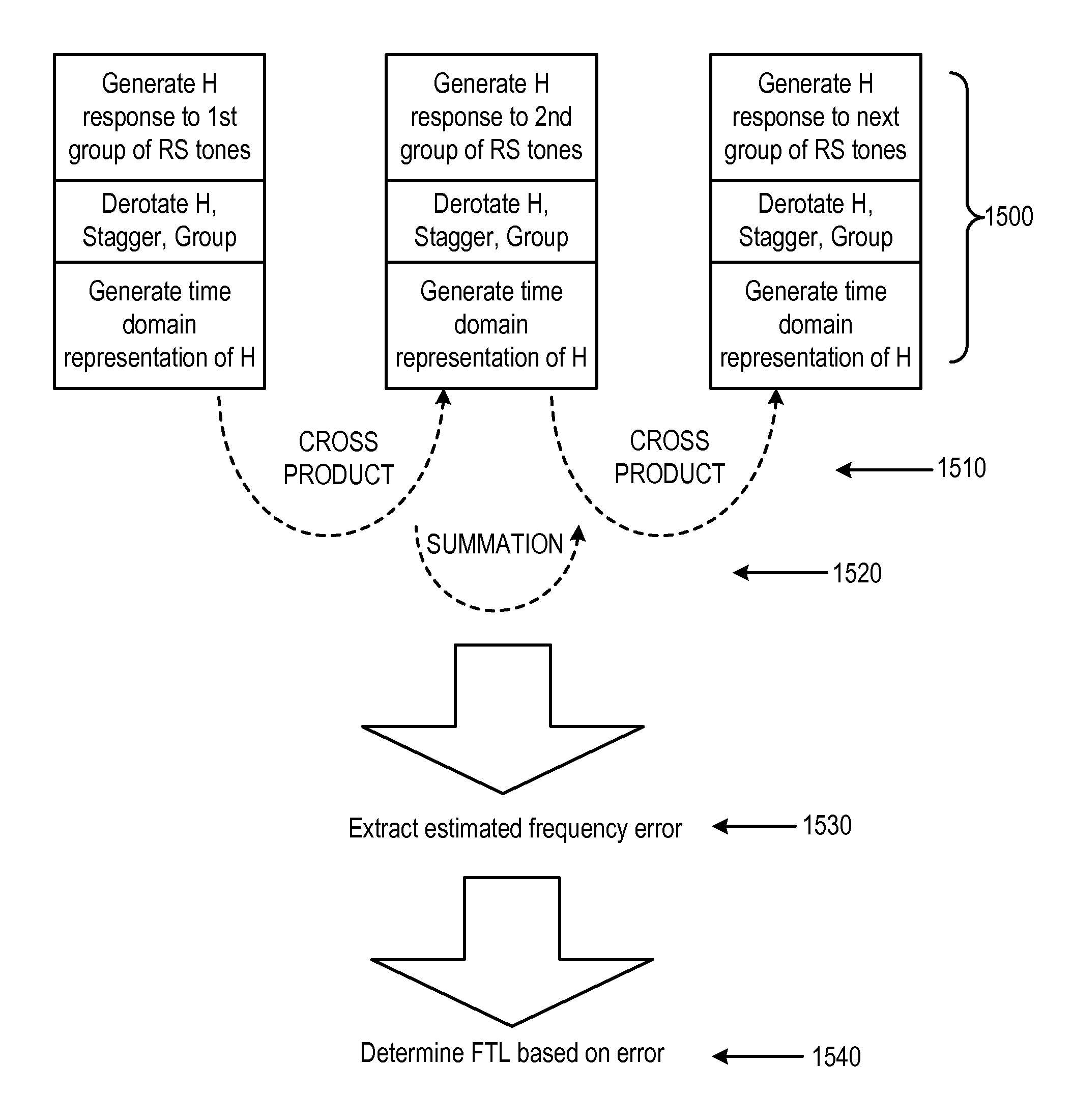
[0009]In one of various aspects of the disclosure, a method for channel estimation using received reference signal (RS) tones in a mobile communications system is provided, comprising: generating frequency domain response expressions (H) for at least one or more sets of RS tones in a communication channel; derotating H by a complex conjugate of the RS tones; combining the frequency domain response expressions to form a staggered frequency domain response expression (Ha,b) of the one or more sets of RS tones; grouping terms of the staggered frequency domain response expression into desired signals A(fe) and phase signals B(d,fe), where fe represents frequency error and d represents a number of chips between RS tones; converting the staggered frequency domain response expression into a time domain expression (ha,b); generating an error function Z(fe) from the time domain expression (ha,b) by applying a cross product between different pairs of RS tone groups (Ha,b, Hb,c, etc.) and summing terms; estimating a frequency error fe from the error function Z(fe); and adjusting a discriminator in a mobile device based on the estimated frequency error for enhanced frequency tracking.
[0010]In another aspect of the disclosure, an apparatus for channel estimation using received reference signal (RS) tones in a mobile communications system is provided, comprising: means for generating frequency domain response expressions (H) for at least one or more sets of RS tones in a communication channel; means for derotating H by a complex conjugate of the RS tones; means for combining the frequency domain response expressions to form a staggered frequency domain response expression (Ha,b) of the one or more sets of RS tones; means for grouping terms of the staggered frequency domain response expression into desired signals A(fe) and phase signals B(d,fe), where fe represents frequency error and d represents a number of chips between RS tones; means for converting the staggered frequency domain response expression into a time domain expression (ha,b); means for generating an error function Z(fe) from the time domain expression (ha,b) by applying a cross product between different pairs of RS tone groups (Ha,b, Hb,c, etc.) and summing terms; means for estimating a frequency error fe from the error function Z(fe); and means for adjusting a discriminator in a mobile device based on the estimated frequency error for enhanced frequency tracking.

Problems solved by technology

SC-FDMA has similar performance and essentially the same overall complexity as those of an OFDMA system.
However, it is well known that the frequency clocks in the UE may not be as accurate as the transmitting AP's clock (either being of inferior quality and / or subject to different conditions from that of the AP, and so forth).
This difference results in frequency error on the UE side.
(1), it can be observed that frequency error fe reduces the desired signal strength and increases the interference level.
It is noted that when the ratio crosses the dB=0 point, the desired signal and the image signal are of equal strength which means that the FTL will not be reliable.
If, however, the pilot tone is not uniformly placed in the frequency domain or the frequency domain placement varies from time to time, this traditional domain filtering approach may be too complex to implement.

Method used


Image

  • Channel impulse response (CIR)-based and secondary synchronization channel (SSC)-based (frequency tracking loop (FTL)/time tracking loop (TTL)/channel estimation
  • Channel impulse response (CIR)-based and secondary synchronization channel (SSC)-based (frequency tracking loop (FTL)/time tracking loop (TTL)/channel estimation
  • Channel impulse response (CIR)-based and secondary synchronization channel (SSC)-based (frequency tracking loop (FTL)/time tracking loop (TTL)/channel estimation

Examples


Embodiment Construction

[0029]For the purposes of the present document, the following abbreviations apply, unless otherwise noted:

[0030]AM Acknowledged Mode

[0031]AMD Acknowledged Mode Data

[0032]ARQ Automatic Repeat Request

[0033]BCCH Broadcast Control CHannel

[0034]BCH Broadcast CHannel

[0035]C- Control-

[0036]CCCH Common Control CHannel

[0037]CCH Control CHannel

[0038]CCTrCH Coded Composite Transport Channel

[0039]CP Cyclic Prefix

[0040]CRC Cyclic Redundancy Check

[0041]CTCH Common Traffic CHannel

[0042]DCCH Dedicated Control CHannel

[0043]DCH Dedicated CHannel

[0044]DL DownLink

[0045]DSCH Downlink Shared CHannel

[0046]DTCH Dedicated Traffic CHannel

[0047]ECI Extended Channel Information

[0048]FACH Forward link Access CHannel

[0049]FDD Frequency Division Duplex

[0050]L1 Layer 1 (physical layer)

[0051]L2 Layer 2 (data link layer)

[0052]L3 Layer 3 (network layer)

[0053]LI Length Indicator

[0054]LSB Least Significant Bit

[0055]MAC Medium Access Control

[0056]MBMS Multimedia Broadcast Multicast Service

[0057]MCCH MBMS point-to-multip...


PUM


Abstract

Methods and systems are disclosed for channel estimation and frequency tracking in mobile communication systems. Particularly, various ways of using the time domain impulse channel response based on the staggered frequency domain pilot tones are presented that enable rapid frequency error estimation and frequency tracking control. A mathematical model is developed that provides a convenient metric for evaluating tolerable frequency error, as well as modes for switching between channel impulse response (CIR)-based and secondary synchronization channel (SSC)-based frequency tracking.

Description

BACKGROUND[0001]1. Field[0002]This disclosure is related to wireless communication systems. More particularly, this disclosure is related to systems and methods for providing improved management of the frequency tracking loop logic / control for mobile systems.[0003]2. Background[0004]Wireless communication systems are widely deployed to provide various types of communication content such as voice, data, and so on. These systems may be multiple-access systems capable of supporting communication with multiple users by sharing the available system resources (e.g., bandwidth and transmit power). Examples of such multiple-access systems include code division multiple access (CDMA) systems, time division multiple access (TDMA) systems, frequency division multiple access (FDMA) systems, 3GPP LTE systems, and orthogonal frequency division multiple access (OFDMA) systems.[0005]Generally, a wireless multiple-access communication system can simultaneously support communication for multiple wire...

Claims


Application Information

Patent Timeline
Patent Type & Authority Patents(United States)
IPC IPC(8): H04L5/12
CPCH04L25/0204H04L25/0212H04L25/022H04L25/0228
Inventor LUO, TAOWEI, YONGBINKIM, BYOUNG-HOON
Owner QUALCOMM INC
Why Eureka
Try Eureka