Exhaust gas purifying catalyst

a technology of exhaust gas and purifying catalyst, which is applied in the direction of physical/chemical process catalysts, other chemical processes, separation processes, etc., can solve the problems of carbon dioxide emitted from the internal combustion engine of the automobile and other problems, and achieve the effect of preventing the loss of zirconia properties, and improving the inhibition

Active Publication Date: 2013-07-30
CATALER CORP
View PDF63 Cites 8 Cited by
  • Summary
  • Abstract
  • Description
  • Claims
  • Application Information

AI Technical Summary

Benefits of technology

[0007]Also, due to a low melting point of alkali metal as the NOx storage material, the alkali metal migrates and is solid-solutioned into the catalyst substrate when the catalyst is heated to high temperatures. As a result, performance of the catalyst is lowered.
[0013]The exhaust gas purifying catalyst of the present invention can inhibit the component (c): an alkali metal or alkaline earth element, from migrating and being solid-solutioned into the catalyst substrate even in high temperatures (for example, 350-450° C.) due to inclusion of the inside layer containing a zirconia oxide. Also, the exhaust gas purifying catalyst of the present invention can exhibit high NOx purification performance in exhaust gas of a lean burn engine.
[0014]In the present invention, the component (a): Rh, is substantially locally existing in the inside layer and the component (b): Pt, is substantially locally existing in the outside layer. Separation of the component (a): Rh, and the component (b): Pt, in this manner can suppress reduction in activity of noble metal and further enhance the NOx purification performance.
[0016]The component (c): an alkali metal or alkaline earth element, and the component (d): an inorganic oxide, may be contained at least in the outside layer. In this manner, the NOx purification performance is further improved.
[0017]The zirconia oxide contained in the inside layer may be an oxide of only zirconia. Other examples of the zirconia oxide are composite oxides of an element selected from a group consisting of alkaline earth elements (for example, Ca and Mg) and rare earth elements (for example, Y, Ce, La and so on), and zirconia. The latter composite oxides are preferable since they can inhibit the component (c): an alkali metal or alkaline earth element, from migrating and being solid-solutioned into the catalyst substrate under the conditions of higher temperatures. In the composite oxides, it is ideal that the additive amount of the element other than zirconia (for example, Ca) is 1.0-8 weight % in terms of oxide, preferably in a range of 1-4 weight %. A weight % of 1.0% or above can further improve the effect of inhibiting the component (c): an alkali metal or alkaline earth element, from migrating and being solid-solutioned into the catalyst substrate. A weight % of 8% or below (preferably, a weight % of 7% or below) can inhibit zirconia properties being lost and the inside layer from being difficult to prepare.
[0022]Examples of the inorganic oxide in the component (d) are, for example, zirconia oxide, alumina, Ce oxide, silica, titania, CeZr composite oxide, and so on. It is preferable that the amount of zirconia oxide contained in the inside layer is in a range of 40-120 g / L. 40 g / L or above of zirconia oxide allows the inside layer to be formed on the surface of the catalyst substrate without producing uncoated portions, and further improves the effect of inhibiting the component (c): an alkali metal or alkaline earth element, from migrating and being solid-solutioned into the catalyst substrate. 120 g / L or below of zirconia oxide allows the outside layer to be easily formed. Alumina is preferable for the component (d): an inorganic oxide, in the outside layer.

Problems solved by technology

In recent years, carbon dioxide emitted from an internal combustion engine of an automobile and others has been a problem from the standpoint of protection of the global environment.

Method used


Image

  • Exhaust gas purifying catalyst
  • Exhaust gas purifying catalyst

Examples


embodiment 1

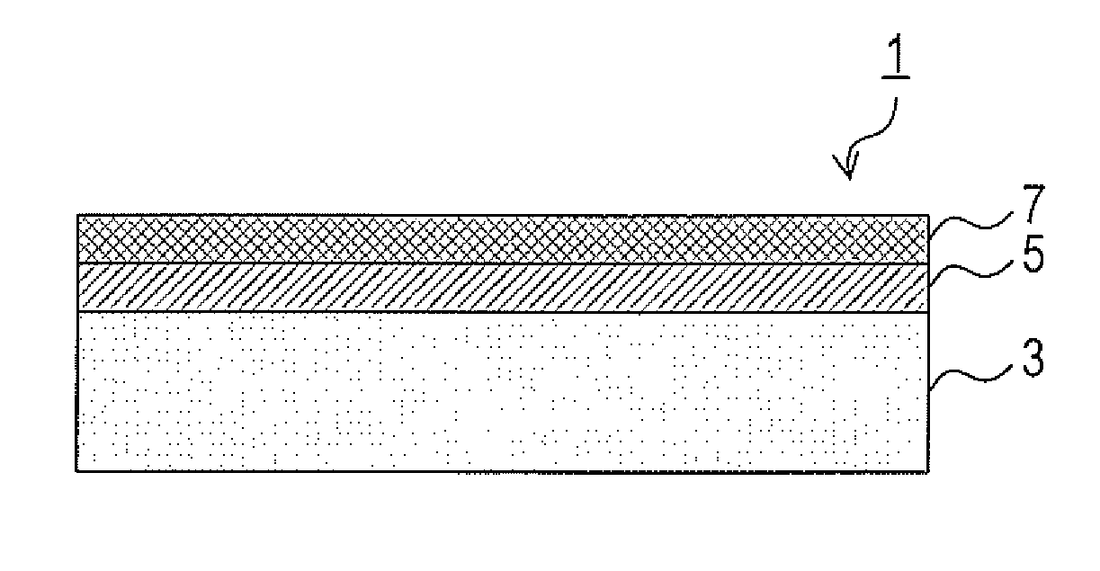
[0033]a) A description will now be given on a structure of an exhaust gas purifying catalyst 1 of an Embodiment 1 with reference to FIG. 1.

[0034]The exhaust gas purifying catalyst 1 includes an inside layer 5 formed on the surface of a substrate (catalyst substrate) 3, and an outside layer 7 further formed on top of the inside layer 5. The inside layer 5 and the outside layer 7 function as a catalyst coating layer. The substrate 3 is a monolith honeycomb substrate having a capacity of 1.0 L and a cell density of 400 cells / in2. The inside layer 5 and the outside layer 7 are formed on the inner face of each cell of the substrate 3.

[0035]The inside layer 5 has the following composition.

[0036]Rh: 0.5 g / L

[0037]Zr-based composite oxide added with 2 weight % of Ca in terms of oxide: 50 g / L

[0038]Ba

[0039]Li

[0040]K

[0041]The outside layer 7 has the following composition.

[0042]Pt: 2 g / L

[0043]alumina: 100 g / L

[0044]ZnTi composite oxide: 100 g / L

[0045]CeZr composite oxide: 20 g / L

[0046]Ba

[0047]Li

[00...

embodiment 2

[0061]The exhaust gas purifying catalyst 1 of an Embodiment 2 has basically the same structure as that of the Embodiment 1, but partly differs in the inside layer 5. Explanation below will focus on the difference. The inside layer 5 in the present embodiment contains an oxide including only zirconia (hereinafter, referred to as “zirconia”) instead of the Zr-based composite oxide added with 2 weight % of Ca in terms of oxide.

[0062]The method of manufacturing the exhaust gas purifying catalyst 1 of the Embodiment 2 is basically the same as that of the Embodiment 1. In the Embodiment 2, a slurry S3 was used in place of the slurry S1 to form the inside layer 5. The slurry S3 was prepared by mixing below listed components.

(Slurry S3)

[0063]Rh nitrate solution: an amount containing 0.5 g of Rh

[0064]zirconia: 50 g

[0065]water: 100 g

embodiment 3

[0066]The exhaust gas purifying catalyst 1 of an Embodiment 3 has basically the same structure as that of the Embodiment 1, but differs in that the outside layer 7 contains not only Pt but Pt (1.5 g / L) and Pd (0.5 g / L) as the noble metal.

[0067]The method of manufacturing the exhaust gas purifying catalyst 1 of the Embodiment 3 is basically the same as that of the Embodiment 1. In the Embodiment 3, the substrate 3 was dipped not in a Pt nitrate solution but in a PtPd nitrate solution (an amount containing 1.5 g of Pt and 0.5 g of Pd) after the outside layer 7 was formed so as to make the outside layer 7 support 1.5 g / L of Pt and 0.5 g / L of Pd. The step of making the substrate 3 support Ba, K and Li thereafter is the same as that of the Embodiment 1.


PUM

PropertyMeasurementUnit
operating temperatureaaaaaaaaaa
weight percentaaaaaaaaaa
temperaturesaaaaaaaaaa

Abstract

An exhaust gas purifying catalyst 1 has a catalyst substrate 3 and catalyst coating layers 5, 7 that are formed on the catalyst substrate 3 and contain (a) Rh, (b) Pt, (c) an alkali metal or alkaline earth element, and (d) an inorganic oxide. The catalyst coating layers 5, 7 has a layered structure including an inside layer 5 where the component (a) is substantially locally existing, and an outside layer 7 where the component (b) is substantially locally existing. The inside layer 5 also contains a zirconia oxide.

Description

CROSS-REFERENCE TO RELATED APPLICATIONS[0001]This application is a U.S. national phase under the provisions of 35 U.S.C. §371 of International Application No. PCT / JP08 / 51124 filed Jan. 25, 2008, which in turn claims priority of Japanese Patent Application No. 2007-016598 filed Jan. 26, 2007. The disclosures of such international application and Japanese priority application are hereby incorporated by reference herein in their respective entireties, for all purposes.TECHNICAL FIELD[0002]The present invention relates to an exhaust gas purifying catalyst that removes toxic substances contained in exhaust gas from an internal combustion engine of an automobile, a motorcycle and others.BACKGROUND ART[0003]In recent years, carbon dioxide emitted from an internal combustion engine of an automobile and others has been a problem from the standpoint of protection of the global environment. A lean burn engine using less fuel provides a promising solution to this problem.[0004]A catalyst includ...

Claims


Application Information

Patent Timeline
Patent Type & Authority Patents(United States)
IPC IPC(8): B01D53/56B01D53/86C01B21/00B01J23/00B01J21/00B01J20/00B01J8/00
CPCB01D53/945B01J23/58B01J23/63B01J35/0006B01J37/0244B01D2255/1021B01D2255/1025B01D2255/202B01D2255/204B01D2255/20715B01D2255/91B01J21/066B01J37/0242Y02T10/22Y02T10/12
Inventor IMAI, HIROTO
Owner CATALER CORP
Why Eureka
Try Eureka