Envelope detector and associated method

a detector and envelope technology, applied in the field of envelope detectors, can solve the problems of large layout area, high power consumption of voltage dividing network, noise and invalid data on the input port of the chip,

Active Publication Date: 2013-07-30
MEDIATEK INC
View PDF3 Cites 10 Cited by
  • Summary
  • Abstract
  • Description
  • Claims
  • Application Information

AI Technical Summary

Problems solved by technology

When no data is transmitted from a remote electronic device / circuit / chip, or a remote electronic device / circuit / chip is disconnected to the input port of the communication system chip, the signal on the input port of the chip contains only noise but not any valid data.
The provision of the voltage dividing network is not only highly power consuming but also occupies a large layout area.
Meanwhile, the mixer 16 multiplying and amplifying the signals is also quite power consuming.
Since the comparator 18 is required to compare high-frequency signals and send out high-frequency results, it is necessary for the comparator 18 to be a high-speed comparator; whereas, the high-speed comparator also suffers from the drawbacks of having high power consumption and a large layout area.
Similarly, for that the sampling circuit 20 samples the high-speed comparison results from the comparator 18 and determines the squelch according to the accumulated sampling results, the sampling circuit 20 needs to operate at an even higher speed sampling clock rate, meaning that a significant power consumption is required.
In addition, misjudgment is likely to be incurred when the squelch is determined solely based on sampling.
The input port of a chip is prone to coupling to various noises and interferences via the cable and / or the trace on the circuit board.
However, regardless of whether the signal on the input port carries real data, the signals are already distorted being affected by the transient state, and any data obtained from data retrieval is hence erroneous.
More specifically, the conventional squelch detector 10 is incapable of eliminating undesirable effects of the common mode noise resultant from the transient state.

Method used


Image

  • Envelope detector and associated method
  • Envelope detector and associated method
  • Envelope detector and associated method

Examples


Embodiment Construction

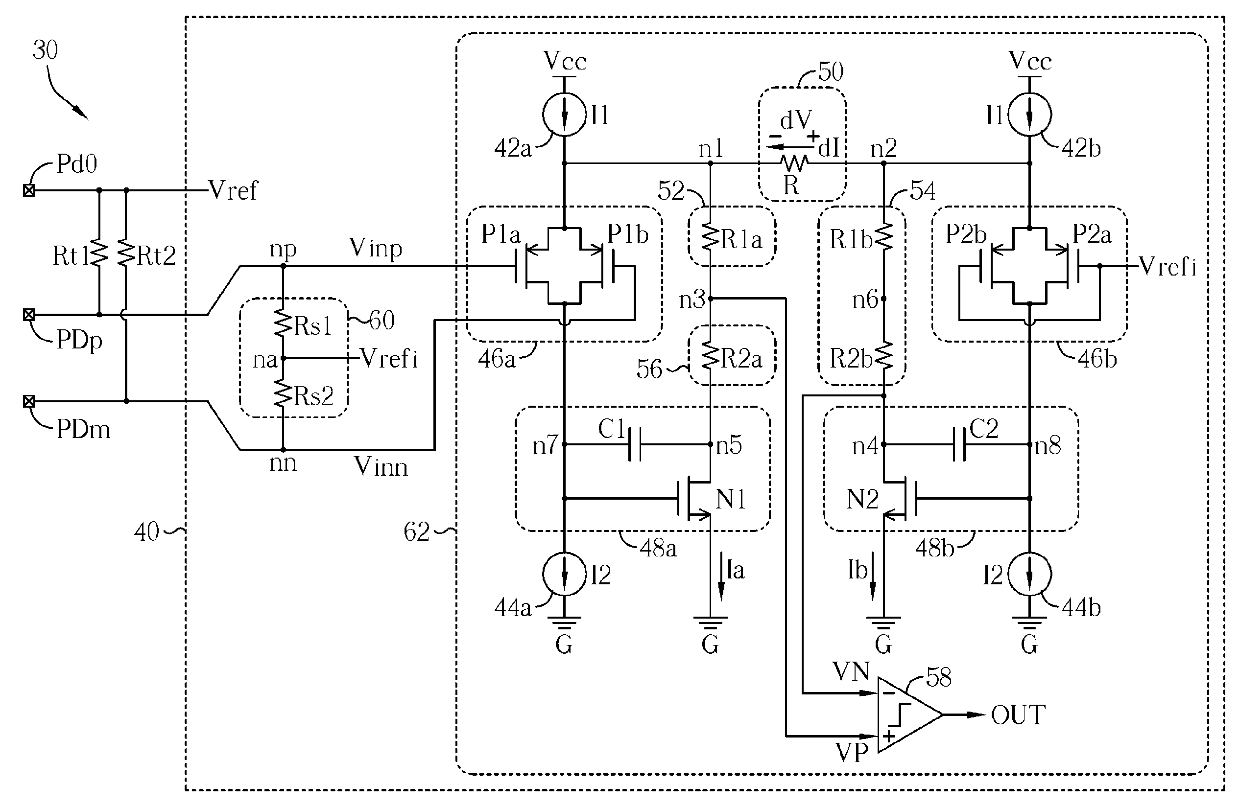
[0031]FIG. 3 shows a schematic diagram of an envelope detector 40 according to an embodiment of the present invention configured in a chip (e.g., an integrated circuit or a die) 30. The chip 30 is packaged in a package 38, and is disposed on a circuit board (e.g., a printed circuit board) 36. A remote electronic device 32 outputs differential data via a pair of output ends TXP and TXM to the chip 30. The output ends TXP and TXM are respectively coupled to a connector of the circuit board 36 via cables 34a and 34b, and then coupled to a pair of differential input pads PDp and PDm via traces on the circuit board as well as pins and bonding of the package 38. The envelope detector 40 configured in the chip 30 performs the squelch detection on paired differential signals Vinp and Vinn on the pads PDp and PDm to provide a signal OUT as the squelch detection signal. The signal OUT from the envelope detector 40 may be utilized in conjunction with a data retrieving digital data circuit (not...


PUM


Abstract

An envelope detecting method performing squelch detection on a pair of differential signal includes: by a voltage divider, providing a real-time reference signal according to a sum of the pair of differential signals; and comparing two comparison signals associated with the real-time reference signals and the pair of differential signals to generate a squelch detection signal.

Description

[0001]This application claims the benefit of Taiwan application Serial No. 100120047, filed Jun. 8, 2011, the subject matter of which is incorporated herein by reference,BACKGROUND OF THE INVENTION[0002]1. Field of the Invention[0003]The invention relates in general to an envelope detector and associated method, and more particularly, to a low-cost, low-power consumption, simple structured and compact envelope detector, suitable for high frequency differential signal squelch detection, and associated method.[0004]2. Description of the Related Art[0005]A modern communication system usually comprises a mechanism for distinguishing whether an input signal is a to-be-processed signal carrying valid information, or simply noise. In general, an input / output (IO) interface of a communication system chip is coupled to an external electronic device / circuit / chip via a cable and / or a trace on a circuit board in order to receive information / messages transmitted from the external electronic devi...

Claims


Application Information

Patent Timeline
Patent Type & Authority Patents(United States)
IPC IPC(8): H03K5/153
CPCH04L25/0292
Inventor HSIEH, YI-CHENG
Owner MEDIATEK INC
Why Eureka
Try Eureka