System and process for transporting LNG by non-self-propelled marine LNG carrier

a marine liquefied natural gas and carrier technology, applied in the direction of container discharging methods, vessel parts, vessel construction, etc., can solve the problems of insufficient power demand to provide effective severe limitation of the degree of lng tank pressure control available, and standard tunnel thrusters, in which a propeller is used

Inactive Publication Date: 2013-08-06
ARGENT MARINE MANAGEMENT
View PDF17 Cites 19 Cited by
  • Summary
  • Abstract
  • Description
  • Claims
  • Application Information

AI Technical Summary

Benefits of technology

[0032]Since the water jet thruster is capable of consuming full power regardless of thrust demands or vessel movement, it will provide a substantial increase in power demand. In this way, significant quantities of LNG boil off gas will be consumed to provide required energy to power the bow thruster at all times of barge movement between ports, thereby providing meaningful LNG cargo tank pressure control. The bow thruster could be either powered by an electric motor, thereby increasing power consumption of the natural gas burning prime movers of the LNG barge generator(s) (if fitted) or, alternately, the bow thruster could be powered by its own natural gas burning prime mover and consume LNG boil off gas directly.
[0034]While insulation is a commonly used approach to reducing the ingress of heat into the LNG cargo, within the practical limits of reducing heat leakage into the LNG cargo tanks by insulation, the above-noted method, in concept, will generally be unable to consume all of the boil off gas necessary to maintain cargo tank pressures. Although the rate of cargo tank pressure increase will be significantly reduced, the cargo tanks will, nonetheless, increase in pressure with the detrimental effects of increased LNG cargo temperatures as described in earlier sections. However, for shorter loaded voyage durations typically less than one day total in loaded voyage duration, the resulting LNG cargo temperature increase may, in fact, be acceptable, in which case the application of the above-noted method alone may be advantageous.
[0042]It is common practice in the industry for a tugboat to push a barge from astern. The barge is often fitted with a notch allowing the tugboat's bow to fit securely into the notch. The tugboat is typically held in the notch by heavy towing wires between the tugboat and the barge. In this arrangement the tugboat and the barge are held in close proximity to each other, which would allow a flexible hose to deliver boil off gas to the propulsion engines of the tugboat to provide required propulsive power. In this manner, sufficient boil off gas can be effectively consumed to provide effective cargo tank pressure control at any desired equilibrium pressure to allow delivery of the LNG cargo at the desired LNG equilibrium temperature.
[0049]Natural gas is restricted to the barge only, eliminating the hazards associated with transferring and / or introducing natural gas aboard or onto the tugboat from the barge and specifically the engine room of the tugboat.
[0050]The engines on the barge burning natural gas are not required to burn combined fuels in varying ratios which provides for simpler controls and greatly increased reliability.
[0052]The power generated by the natural gas burning engine(s) fitted on the LNG barge is limited to the power available from burning available boil off gas only, thereby maximizing LNG cargo delivery. The additional power required to meet the demands of the tugboat's electric propulsion motors, as well as other electric power demands, can be provided, as needed, by the tugboat's fuel oil burning engines.

Problems solved by technology

When transiting from port to port, the power demands of the LNG barge are limited, thereby severely limiting the degree of LNG tank pressure control available.
High power consumers such as cargo pumps are only utilized in port during discharging and, therefore, will not provide sufficient power demand to provide for effective LNG tank pressure control.
Standard tunnel type thrusters, in which a propeller is housed in a tunnel in the fore part of the vessel mounted transversely in the vessel, lose effectiveness with relatively small forward or aft speeds of the barge.
The bow thruster could be either powered by an electric motor, thereby increasing power consumption of the natural gas burning prime movers of the LNG barge generator(s) (if fitted) or, alternately, the bow thruster could be powered by its own natural gas burning prime mover and consume LNG boil off gas directly.

Method used


Image

  • System and process for transporting LNG by non-self-propelled marine LNG carrier
  • System and process for transporting LNG by non-self-propelled marine LNG carrier
  • System and process for transporting LNG by non-self-propelled marine LNG carrier

Examples


Embodiment Construction

[0118]The particulars shown herein are by way of example and for purposes of illustrative discussion of the embodiments of the present invention only and are presented in the cause of providing what is believed to be the most useful and readily understood description of the principles and conceptual aspects of the present invention. In this regard, no attempt is made to show structural details of the present invention in more detail than is necessary for the fundamental understanding of the present invention, the description taken with the drawings making apparent to those skilled in the art how the several forms of the present invention may be embodied in practice.

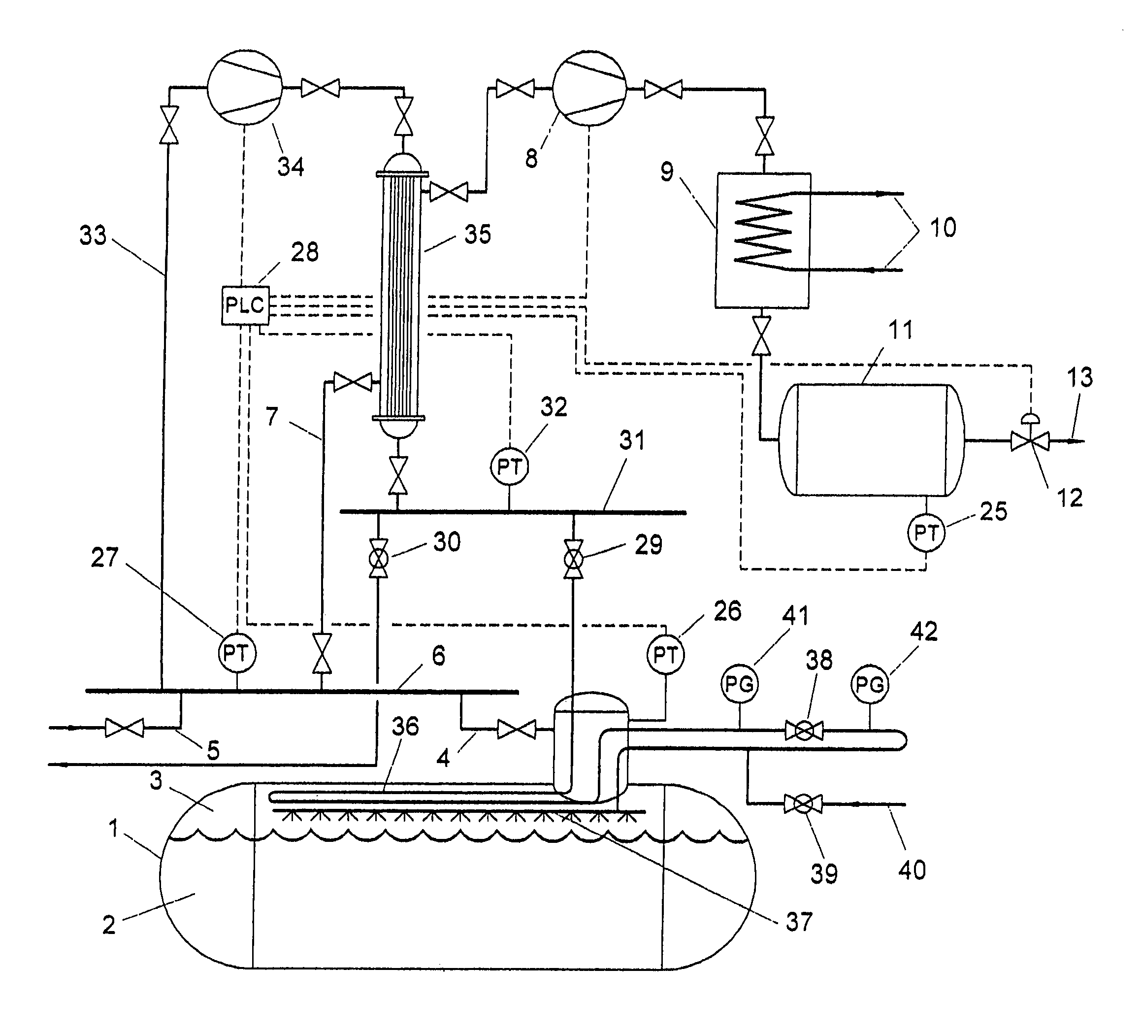
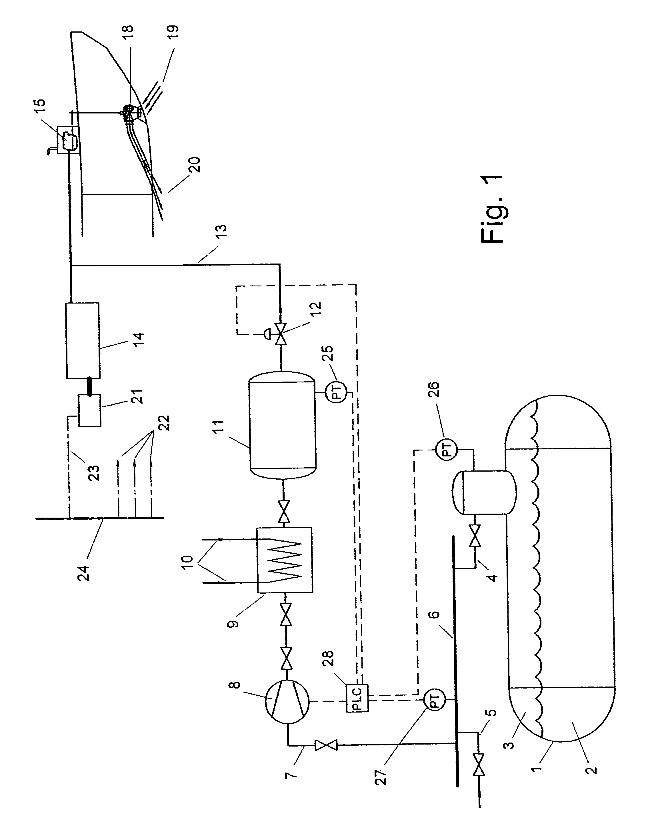
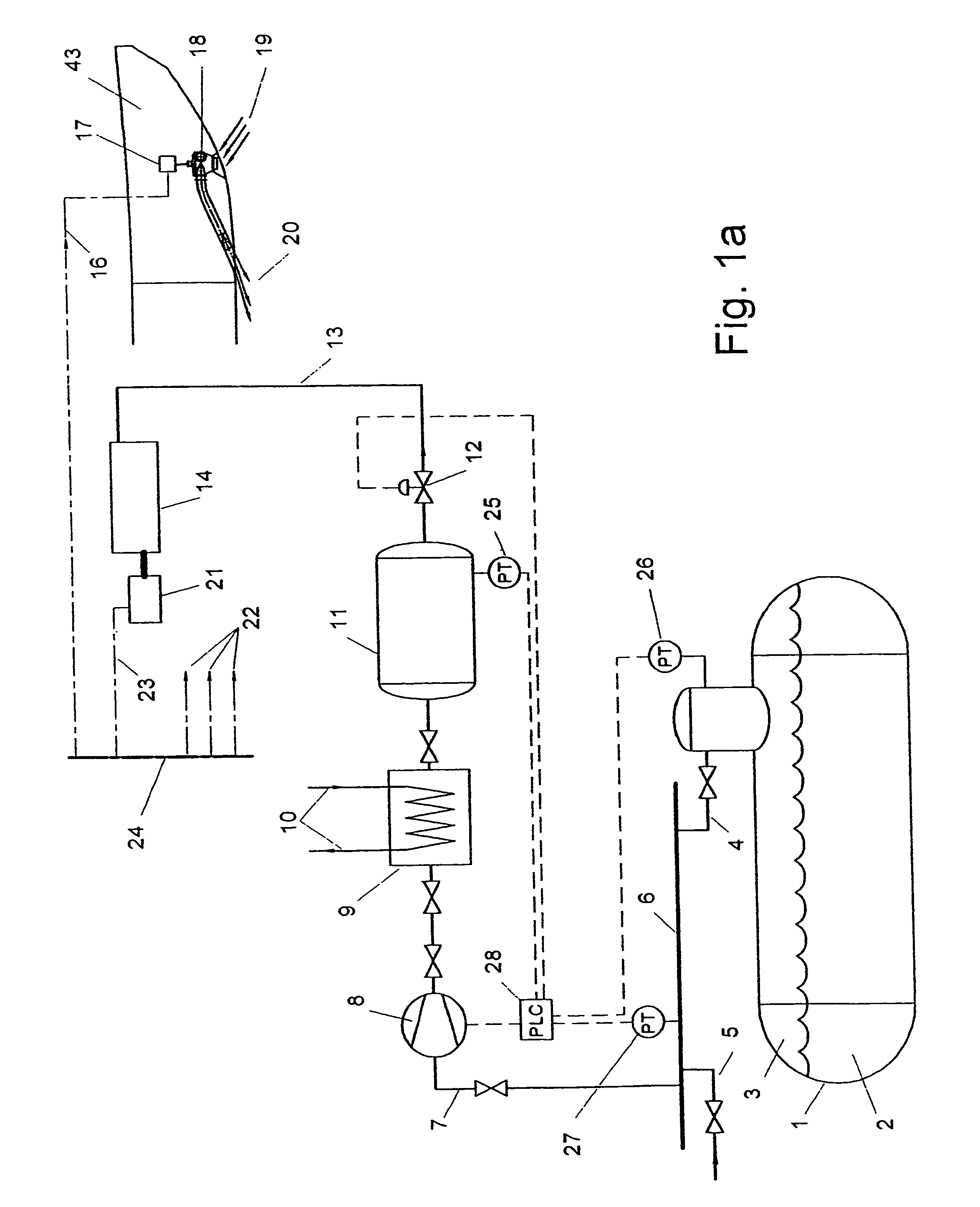
[0119]FIG. 1 shows a first non-limiting arrangement according to the invention. Liquid Natural Gas (LNG) 2 is contained in one or more insulated LNG tank(s) 1. The insulated tanks maybe of the pressure vessel type such as cylindrical or multi-lobe tanks as is common for pressurized liquefied gas carriers or of the non-pre...


PUM


Abstract

Marine LNG carrier and method of operating the marine LNG carrier. The LNG carrier carries LNG in at least one tank. Gas composed of evaporated LNG within the at least one tank is removed. The gas is fed to at least one gas consuming prime mover of the LNG carrier. Power is provided with the at least one gas consuming prime mover. This Abstract is not intended to define the invention disclosed in the specification, nor intended to limit the scope of the invention in any way.

Description

CROSS-REFERENCE TO RELATED APPLICATIONS[0001]The present application claims the benefit of U.S. Provisional Patent Application No. 60 / 608,913, filed on Sep. 13, 2004 under 35 U.S.C. §119(e), the disclosure of which is expressly incorporated by reference herein in its entirety.BACKGROUND OF THE INVENTION[0002]1. Field of the Invention[0003]The invention relates to a method of operating a marine liquefied natural gas (LNG) carrier in which LNG is carried in at least one tank, wherein the method includes removing gas generated by evaporation of the LNG within the at least one tank, feeding the gas to at least one gas consuming prime mover of the LNG carrier, and providing power, with the at least one gas consuming prime mover, to at least one thruster. The at least one thruster is capable of consuming full power at all times notwithstanding actual thrust requirements of the LNG carrier.[0004]The invention also relates to a method of operating a marine liquefied natural gas (LNG) carrie...

Claims


Application Information

Patent Timeline
Patent Type & Authority Patents(United States)
IPC IPC(8): F17C3/10F17C13/08
CPCB63B25/16F01K25/08F17C9/04B63B35/70B63H11/02B63H11/102B63H21/17B63J2099/003F17C2221/033F17C2223/0161F17C2223/033F17C2250/032F17C2250/043F17C2265/03F17C2265/034F17C2265/036F17C2265/037F17C2265/066F17C2270/0105Y02T70/5263Y02T70/50
Inventor VAN TASSEL, GARY W.
Owner ARGENT MARINE MANAGEMENT
Why Eureka
Try Eureka