
Volumetric physiological measuring system and method

a physiological measurement and volumetric technology, applied in the direction of respiratory organ evaluation, electrical/magnetic measuring arrangement, compasses, etc., can solve the problems of inability to obtain reliable data, crude and inaccurate measurements, and inability to use airway-based techniques to achieve reliable data, reduce circuit cooling and power supply capacity, and minimize the total power consumption of amplifier units

Inactive Publication Date: 2013-08-06
VOLUSENSE AS
View PDF42 Cites 4 Cited by
  • Summary
  • Abstract
  • Description
  • Claims
  • Application Information

AI Technical Summary

Benefits of technology

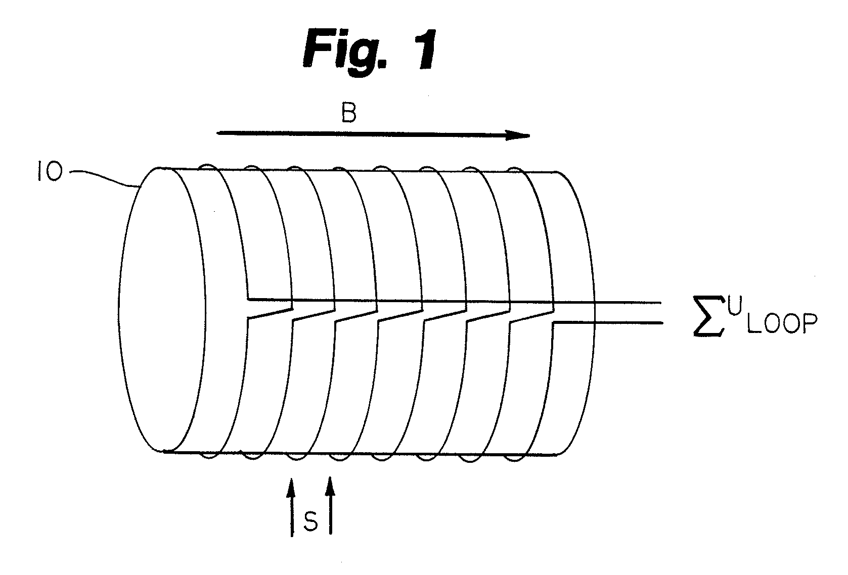
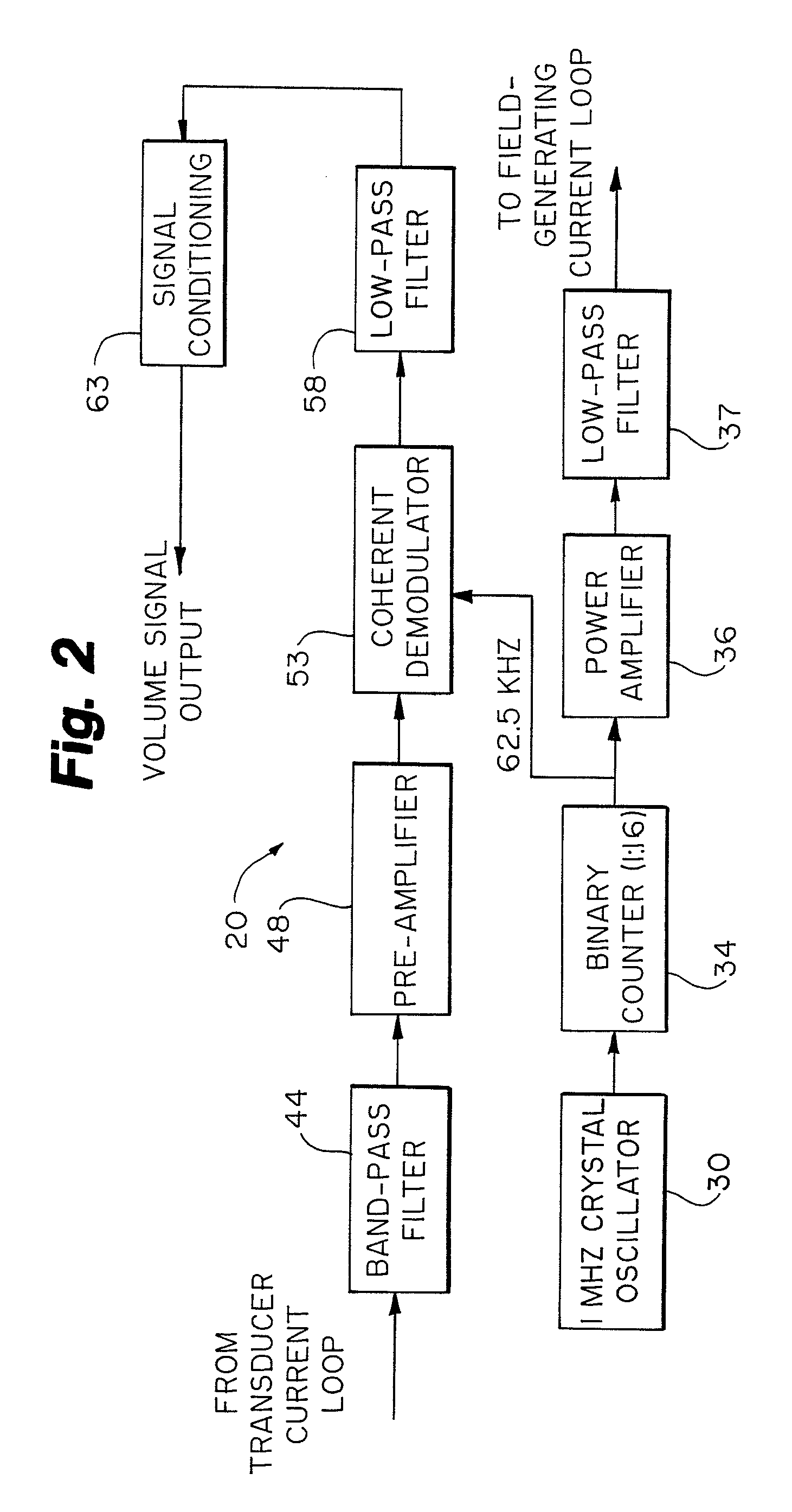
The invention is a system for measuring the volume of a patient's body or other object using electrical loops. The system is designed to be simple and compact, with only one embodiment being described here. The loops are placed around the patient's body and the signal is measured using a low-pass filter. The system is easy to use and can be integrated into a computer for further analysis and processing. The technical effects of the invention include reduced complexity, improved accuracy, and reduced interference with other electronic equipment.

Problems solved by technology

Unfortunately these measurements are often crude and inaccurate, or at best rely upon outmoded technical modalities or upon unreliable.
For long-term monitoring purposes, the airway-based techniques are inappropriate since they interfere with normal breathing and are unpleasant for the patient.
Although airway-based techniques are currently used in patients dependent on respiratory-assist devices there may be less intrusive and more reliable means of obtaining such data.
Unfortunately, this is not the case for the cross-sectional area variations of the human chest or abdomen that are caused by respiration.
Common to all area-based methods is a considerable uncertainty in the calculations of volume variations from the estimated area variations.
The calibration procedure depends highly upon patient cooperation to obtain coefficients for both chest and abdominal measurement sites, and is virtually inapplicable to small children, patients with dyspnea (shortness of breath), and unconscious patients.

Method used


Image

  • Volumetric physiological measuring system and method
  • Volumetric physiological measuring system and method
  • Volumetric physiological measuring system and method

Examples


example 1

[0058]A circular electrical conductor loop with a radius of 1.5 meters was placed on the floor. An alternating current of 0.1 A with a frequency of 100 kHz was fed through the conductor from a signal generator. A small, 10×10 cm (100 cm2) square conductor loop was connected to the input of a broadband signal amplifier with a gain of 40 dB, and the output from this amplifier was passed through a narrow 100 kHz band-pass filter with no gain. The output signal from the filter was presented on an oscilloscope screen, where voltages could be read by cursors. When the small loop was positioned flat on the floor in the center of the larger current loop, a voltage of 5 mV p / p was measured. This voltage remained essentially constant when the small loop was elevated 50 cm above the floor, and it also remained constant when the small loop was moved up to 50 cm in any horizontal direction away from the center of the large current loop. Another square loop, measuring 14.1×14.1 cm, with an area o...

example 2

[0059]The same conductor loops as described in Example 1 were used, but the 0.1 A current from the signal generator was fed to the 100 cm2 loop, and the large loop on the floor was connected to the input of the 40 dB broadband amplifier. The small loop was positioned as explained in Example 1. The same general relations between induced voltage and loop position and area was observed as in Example 1, however the voltages were reduced to 250 μV when using the 100 cm2 loop, and 500 μV when using the 200 cm2 loop.

example 3

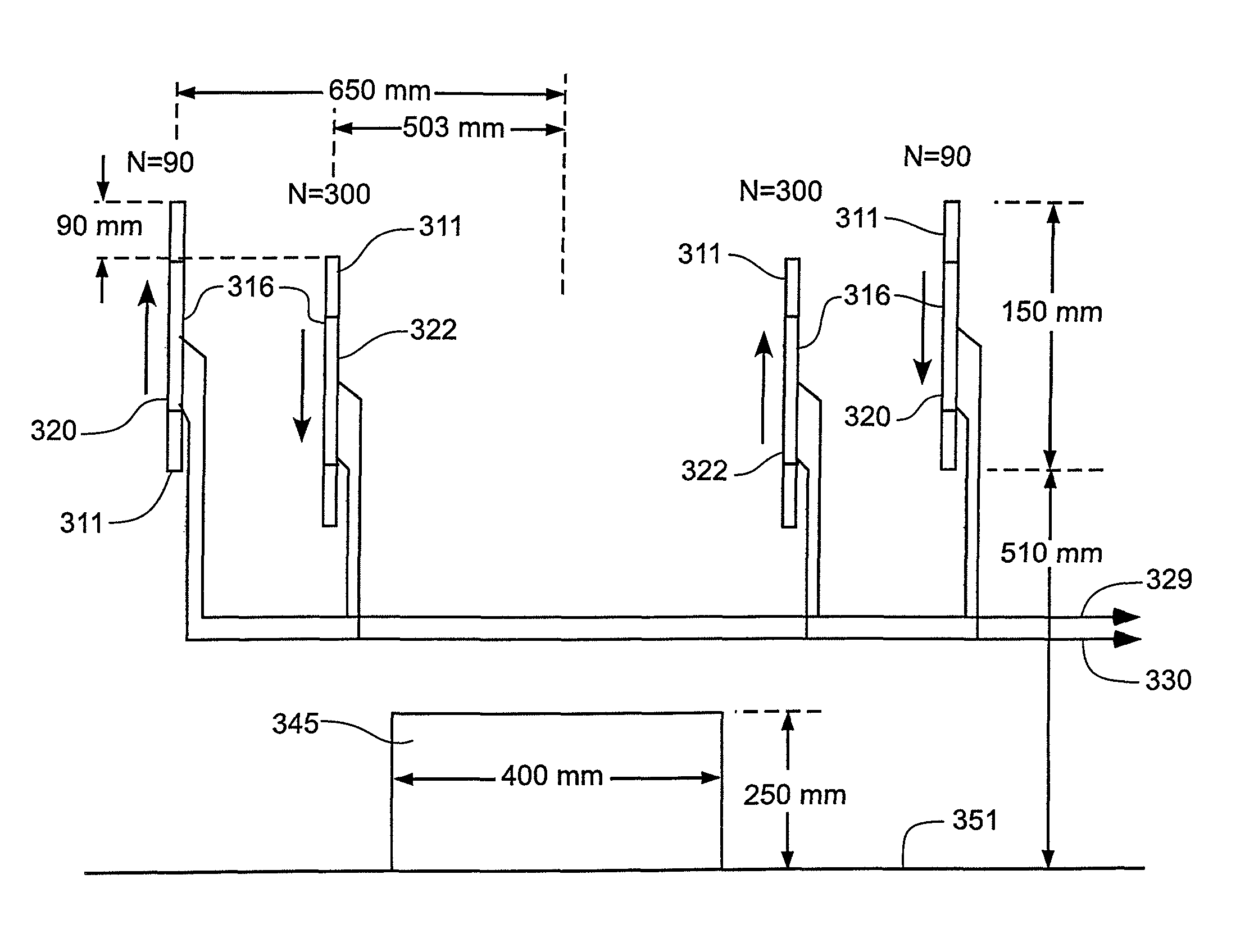
[0060]Referring to FIG. 11, three identical cylindrical ferrite rods 175 with a diameter of 8 mm, length of 150 mm and permeability of 100 were arranged along a straight horizontal line with a common axis. The end-to-end horizontal spacing between each rod was 50 cm. The two outer coils were equipped with 163 turns of lacquer-insulated 0.1 mm copper wire evenly distributed along a central 8 cm segment of the rod, while the center rod had 100 turns arranged in the same manner. The coils were electrically connected in series, and care was taken to assure identical current directions in all coils. The serially connected coils were then tuned to parallel resonance at 100 kHz with a common capacitor 177 of about 10 nF. An oscilloscope directly monitored the signal from the resonant circuit. A 10 cm×10 cm current loop carrying a 100 kHz alternating current of 0.1 A was positioned adjacent to the coil assembly, keeping the orientation of the loop perpendicular to the ferrite rods common ax...


PUM

PropertyMeasurementUnit
lengthaaaaaaaaaa
currentsaaaaaaaaaa
cut-off frequencyaaaaaaaaaa

Abstract

A system and method for measuring volumes and areas using electromagnetic induction techniques. A current is generated and fed into one of two coil assemblies to induce voltage into another coil assembly to provide accurate values for volume or area.

Description

CROSS-REFERENCE TO RELATED APPLICATIONS[0001]This application is a continuation of U.S. patent application Ser. No. 10 / 671,011, filed Sep. 25, 2003, now U.S. Pat. No. 7,390,307, which is a continuation-in-part of U.S. Divisional patent application Ser. No. 10 / 087,302, filed Feb. 28, 2002, now U.S. Pat. No. 6,945,941, which in turn is a divisional application of U.S. patent application Ser. No. 09 / 428,358, filed Oct. 28, 1999, now U.S. Pat. No. 6,374,667, issued Apr. 23, 2002, which are incorporated herein by reference.FIELD OF THE INVENTION[0002]The invention relates to a system and method for accurate measurements of volume and area of objects, utilizing electromagnetic induction techniques.BACKGROUND OF THE INVENTION[0003]Numerous opportunities exist in which accurate measurements of volume and area are essential, particularly of objects or portions of objects having variable volumes or areas. For example, in the field of medicine, the recording of breathing volumes in patients is...

Claims


Application Information

Patent Timeline
Patent Type & Authority Patents(United States)
IPC IPC(8): A61B5/103A61B5/117G01N27/72G01R33/12G01R33/00G01R33/02A61B5/08G01F1/56G01F1/716G01F1/58G01P5/08G01F17/00A61B5/05A61B5/06A61B5/113G01B7/00G01B7/28G01B7/32
CPCA61B5/06A61B5/1135A61B5/091A61B5/7203A61B5/7278A61B5/05A61B5/6802A61B5/1073
Inventor ERIKSEN, MORTENERIKSEN, ERIK
Owner VOLUSENSE AS
Learn More